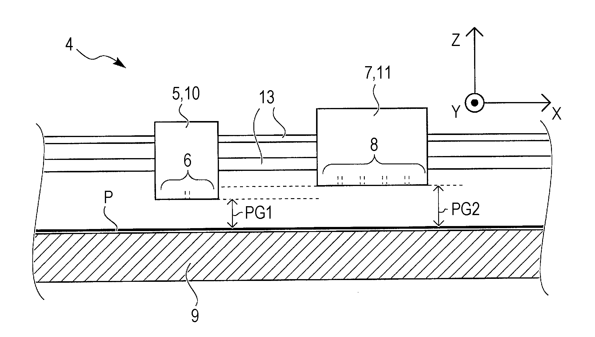
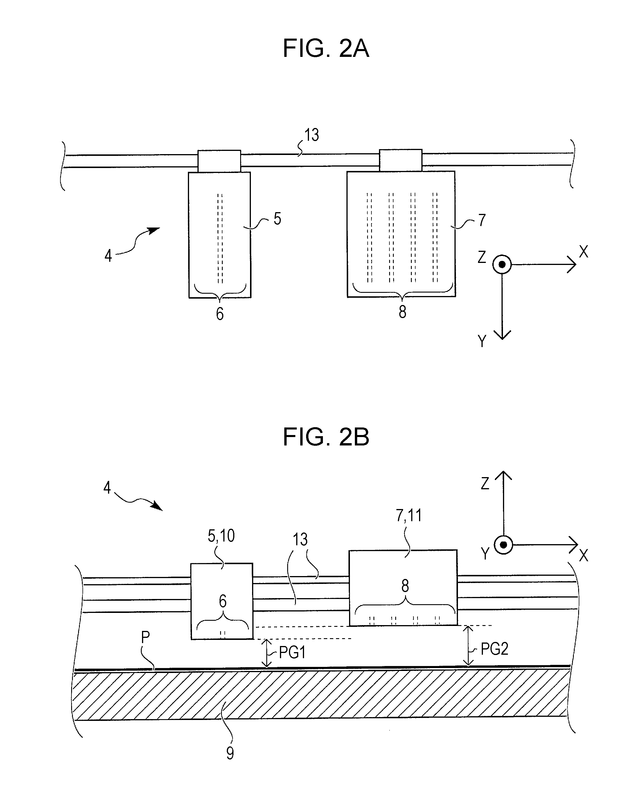
[0009]A recording apparatus according to a first aspect of the invention includes: a first nozzle for ejecting a first type of liquid for base
coating onto a recording target medium; and a second nozzle for ejecting a second type of liquid onto a base formed as a result of the base coating; wherein a distance between the first nozzle and the recording target medium is shorter than a distance between the second nozzle and the recording target medium. Since there is the above relationship therebetween, a recording apparatus according to the above aspect of the invention makes the distance (PG1) between the first nozzle and the recording target medium at the time of base coating (basecoat printing) approximately equal to an actual distance (PG2′) between the second nozzle and the surface of the base coating layer at the time of recording (printing) thereon, thereby making it possible to improve recording quality. In other words, it is possible to avoid problems caused by a decrease, the amount of which is equal to the thickness of the base coating layer, in the distance between the nozzle and the area where the discharged liquid droplets land on the recording target medium. For example, there is no risk of abrasion of the layer on the recording target medium by the nozzle surface of the
recording head. The first nozzle and the second nozzle may be formed in a single
recording head. Alternatively, they may be formed in separate recording heads.
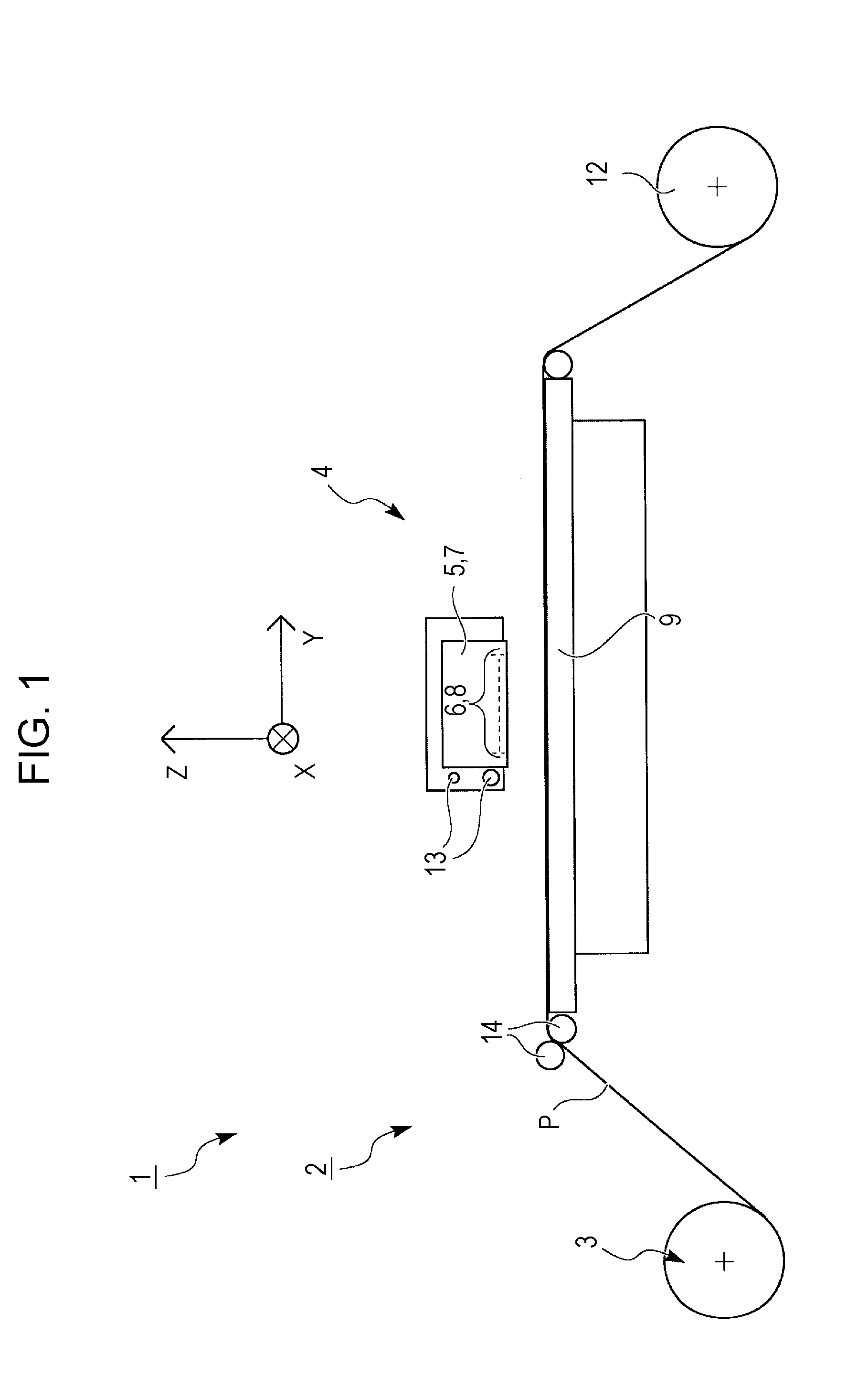
[0010]In a second mode of the invention, preferably, a recording apparatus according to the above aspect of the invention further includes a first
recording head that has the first nozzle and a second recording head that has the second nozzle, wherein the first recording head is separated from the second recording head. In addition to the operational effects produced by the first aspect of the invention, such a preferred structure makes it possible to perform recording operation by the first recording head and recording operation by the second recording head separately, which is useful.
[0011]In a third mode of the invention, preferably, a recording apparatus according to the second mode of the invention described above further includes a distance changer for changing a distance between the first recording head and the recording target medium. In addition to the operational effects produced by the second mode of the invention, such a preferred structure makes it possible to set the distance between the first recording head and the recording target medium at an appropriate value. For example, when the first type of liquid is ejected to form a
liquid layer that is made up of three tiers, it is possible to set the distance between the first recording head and the recording target medium at an appropriate value. Therefore, there is no risk that any foreign particle, object, etc. on the recording target medium sticks to the first recording head because of a too close distance therebetween. Since there is no risk of such sticking, “missing dot” does not occur. Herein, the term “missing dot” means the following phenomenon: when a liquid droplet discharged from a certain nozzle is trapped by a
foreign object sticking to the nozzle and thus does not land on a recording target medium, no dot (spot of the landing of a liquid droplet) is formed at the point where the droplet is supposed to land.
[0012]In a fourth mode of the invention, preferably, in any of the first aspect, the second mode, and the third mode of the invention, each of the first type of liquid and the second type of liquid is photo-curable ink. Herein, the term “photo-curable ink” means ink that cures (solidifies) when exposed to light. An example of photo-curable ink is
ultraviolet ray curing (solidification) ink (UV ink), which cures (solidifies) when exposed to
ultraviolet rays. A change in the volume of
ultraviolet ray curing ink in the process of curing (solidification) is far smaller than that of dye ink and
pigment ink, each of which cures (solidifies) as a result of the
vaporization of its
solvent. In addition to the operational effects produced by the above
modes / aspect of the invention, since the liquid is photo-curable ink, the following effects can be expected with such a preferred structure. The base coating layer is formed by means of the first type of liquid. As compared with the distance before the forming of the base coating layer, there is a change in terms of distance, specifically, a change into the distance between the second nozzle, from which the liquid is ejected thereafter, and the surface on which the discharged liquid droplets land (i.e., the surface of the base coating layer) over the recording target medium. Therefore, the structure having the above relationship regarding the distance is especially effective for this mode.

