

Electric field assisted magnetic recording
a technology of electric field and magnetic recording, applied in special recording techniques, instruments, record information storage, etc., can solve the problems of limiting factors, small field gradients, and broader field profiles, and achieve the effect of reducing coercivity magnetic layer, high area density, and reducing magnetic field
- Summary
- Abstract
- Description
- Claims
- Application Information
AI Technical Summary
Benefits of technology
Problems solved by technology
Method used
Image

Examples
Embodiment Construction
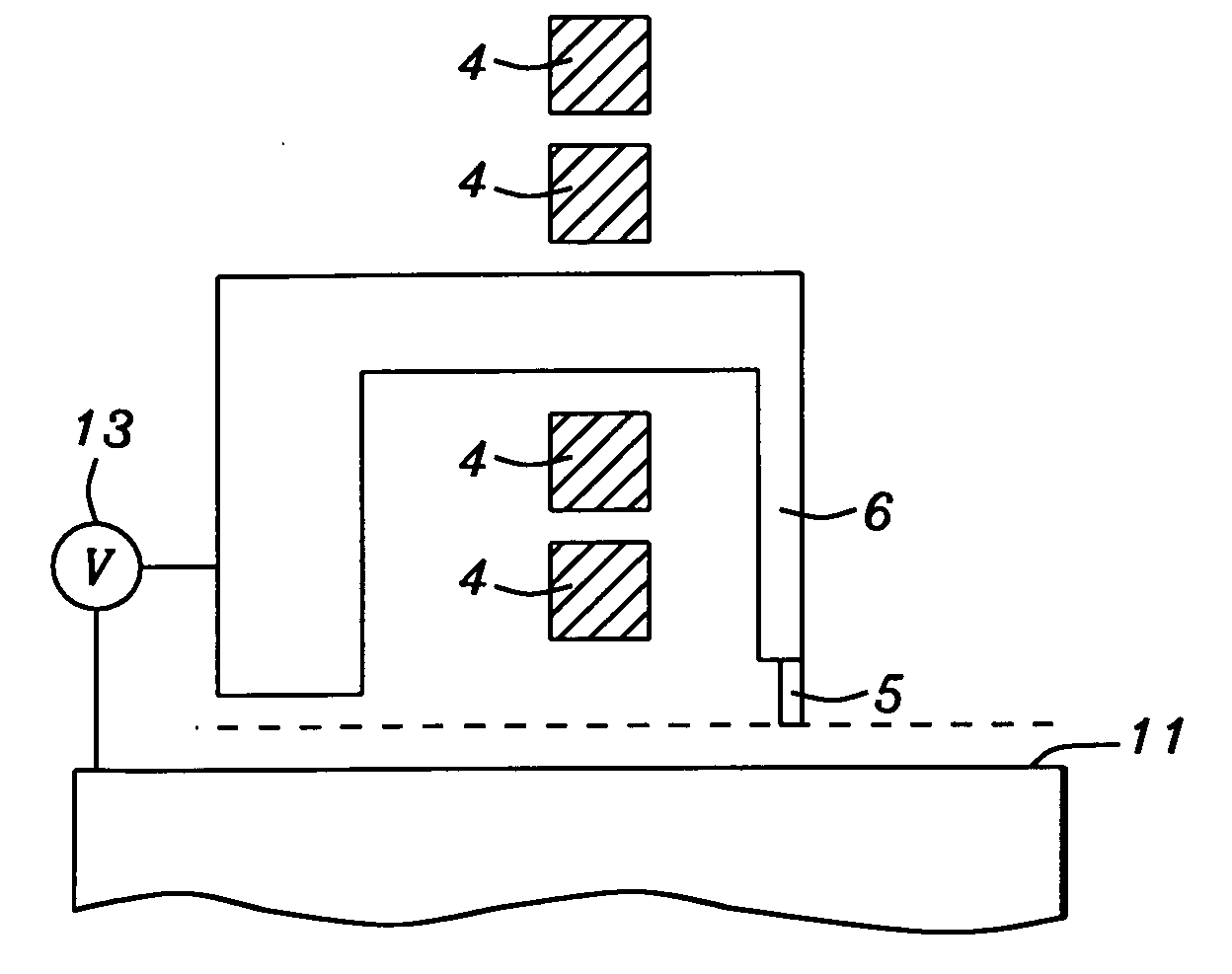
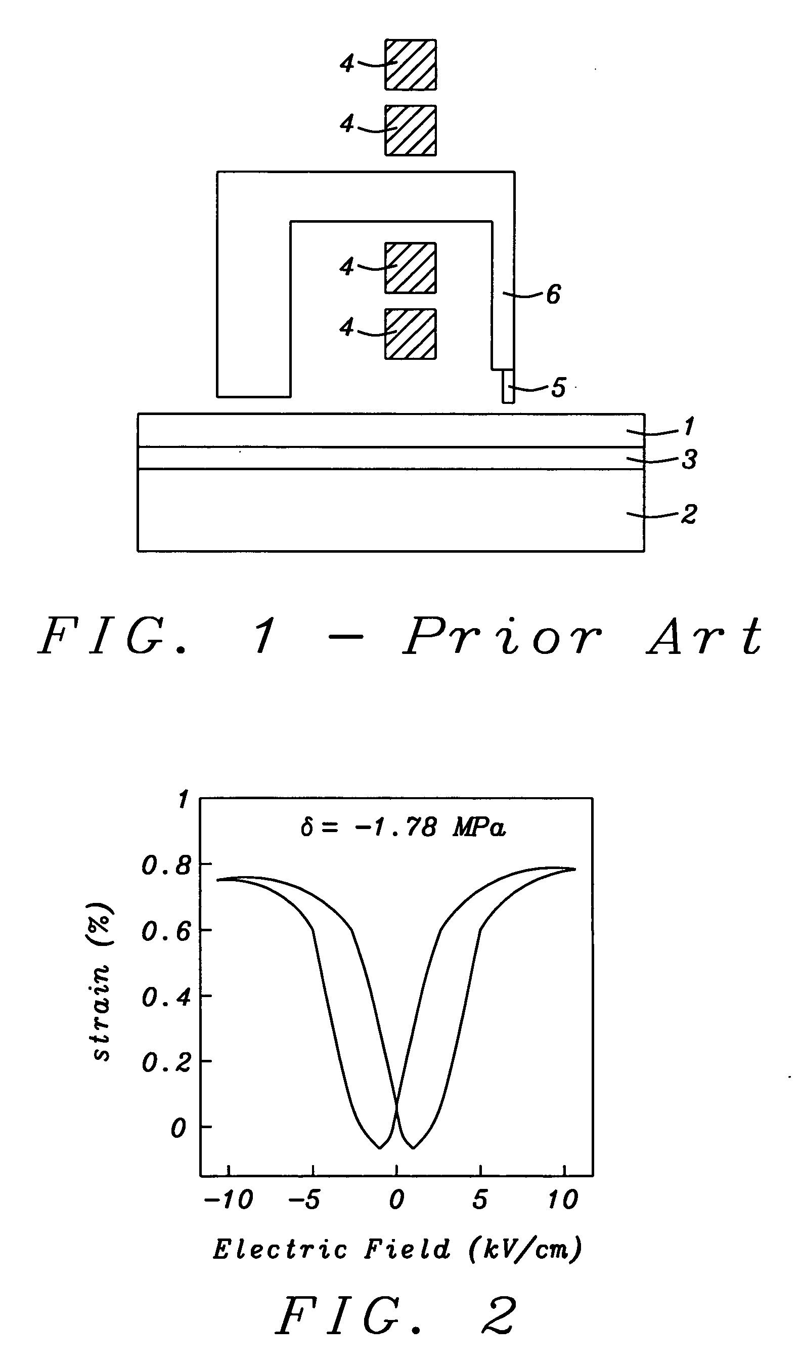
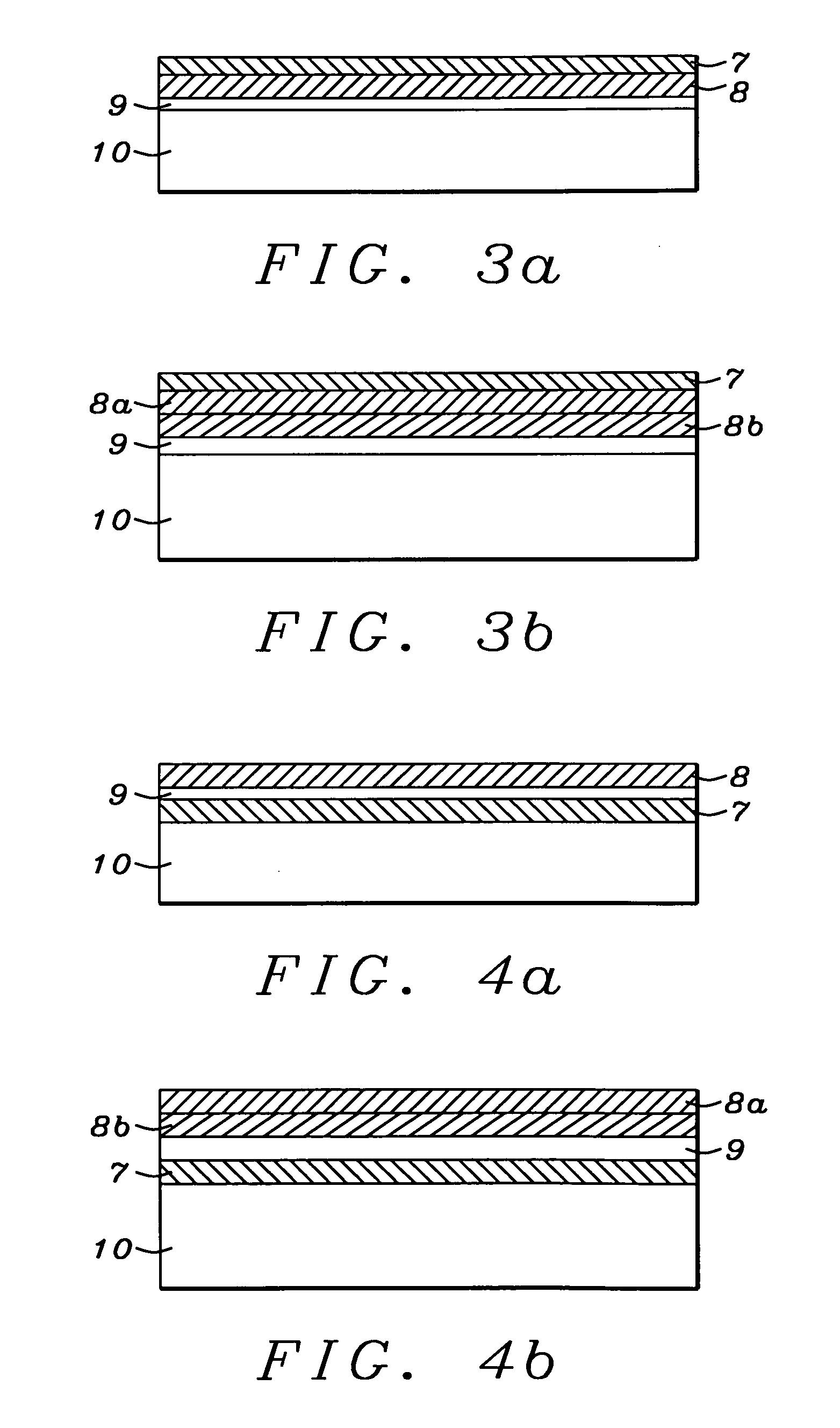
[0021]This invention describes the use of electrostrictive material in combination with magnetostrictive material to enable the electric field assisted magnetic recording at high area density. To accomplish this process, an electric field is created by imposing a voltage difference between a recording head and a recording medium so that a deep sub-micron sized localized region of electric polarization is produced in a layer of electrostrictive material that is part of the recording medium. This polarized region in turn causes a strong localized strain in that layer. This localized strain is then coupled, through physical contact, with a magnetostrictive layer that is also a part of the recording medium. The coupling of this strain to the magnetostrictive layer thereupon produces a stress induced magnetic anisotropy in the magnetostrictive layer. The magnetostrictive layer can also be the recording (storage) layer, or it can itself be magnetically exchange coupled to an adjacent reco...
PUM
| Property | Measurement | Unit |
|---|---|---|
| electric field | aaaaa | aaaaa |
| electric field | aaaaa | aaaaa |
| electric field | aaaaa | aaaaa |
Abstract
Description
Claims
Application Information