Multi-Layer Optical Disc, and Recording Method and Apparatus for Multi-Layer Optical Disc

a multi-layer optical disc and recording method technology, applied in the field of multi-layer optical discs, can solve the problems of not contributing to the improvement of the recording quality of data in either case, and the “optimum recording power value” calculated in this manner is not suitable, so as to achieve the effect of improving the recording quality of data and favorable power

Inactive Publication Date: 2008-05-01
HITACHI CONSUMER ELECTRONICS CORP
View PDF3 Cites 13 Cited by
  • Summary
  • Abstract
  • Description
  • Claims
  • Application Information

AI Technical Summary

Benefits of technology

[0008] According to the present invention, even if recording is carried out randomly to a multi-layer disc and the recorded portion and unrecorded portion in each layer are randomly distributed and the transmissivity becomes random, it is possible to write with a favorable power and improve the recording quality of the data.

Problems solved by technology

However, the “optimum recording power value” calculated in this manner is not a suitable one when recording into a “data area of the lower layer” with a laser beam passing through an unrecorded “data area of the upper layer”.
However, since the “optimum recording power value” calculated in the OPC of JP-A-2000-311346 is the optimum value for either one of the above-described cases, the “optimum recording power value” is not effective for the other case, thus causing a problem of not contributing to an improvement in the recording quality of data in either one of the cases.

Method used


Image

  • Multi-Layer Optical Disc, and Recording Method and Apparatus for Multi-Layer Optical Disc
  • Multi-Layer Optical Disc, and Recording Method and Apparatus for Multi-Layer Optical Disc
  • Multi-Layer Optical Disc, and Recording Method and Apparatus for Multi-Layer Optical Disc

Examples


first embodiment

[0015] A multi-layer optical disc that is the present invention is described with a recording type optical disc having a four layer structure being as an example, using FIG. 1.

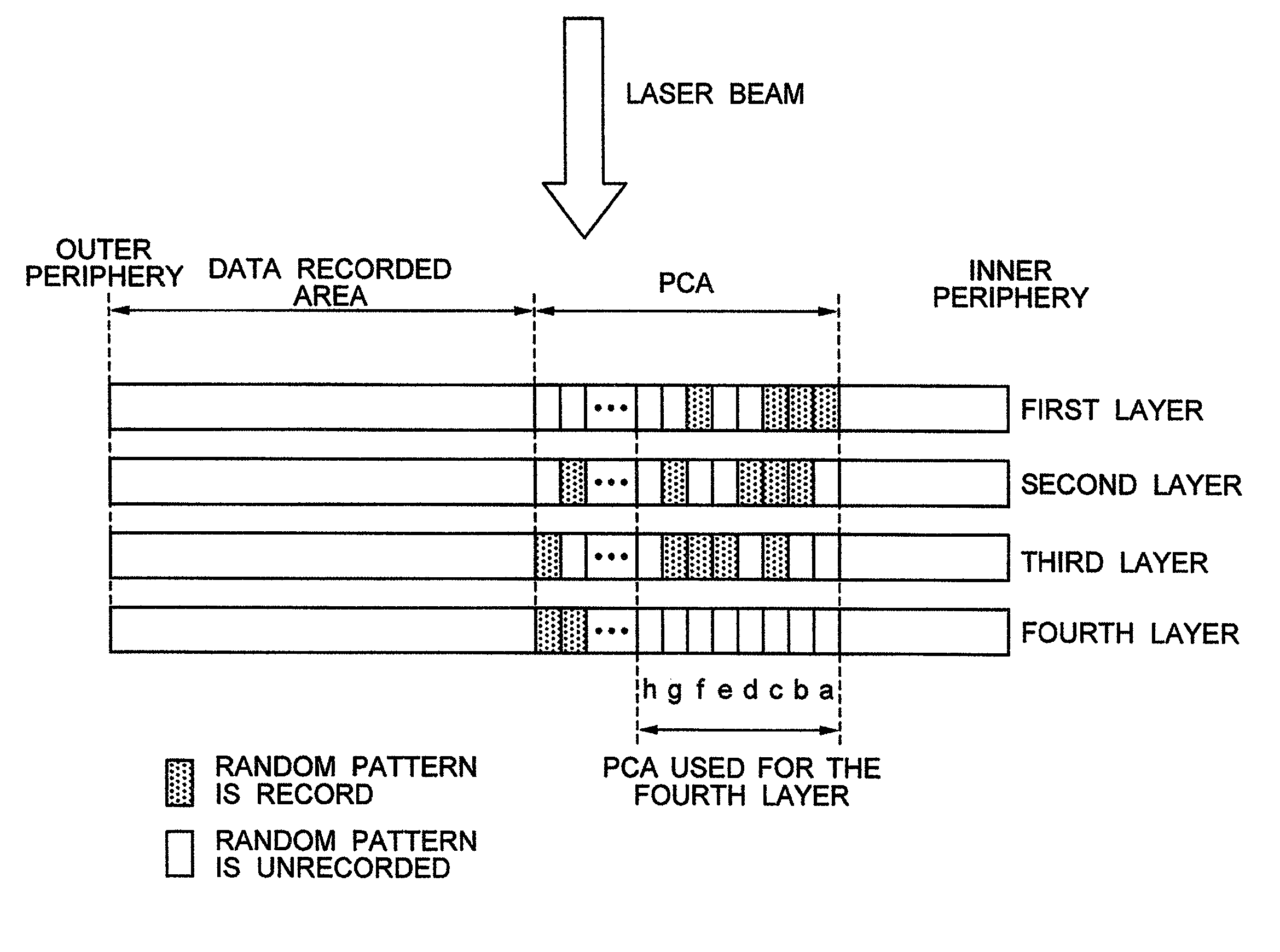
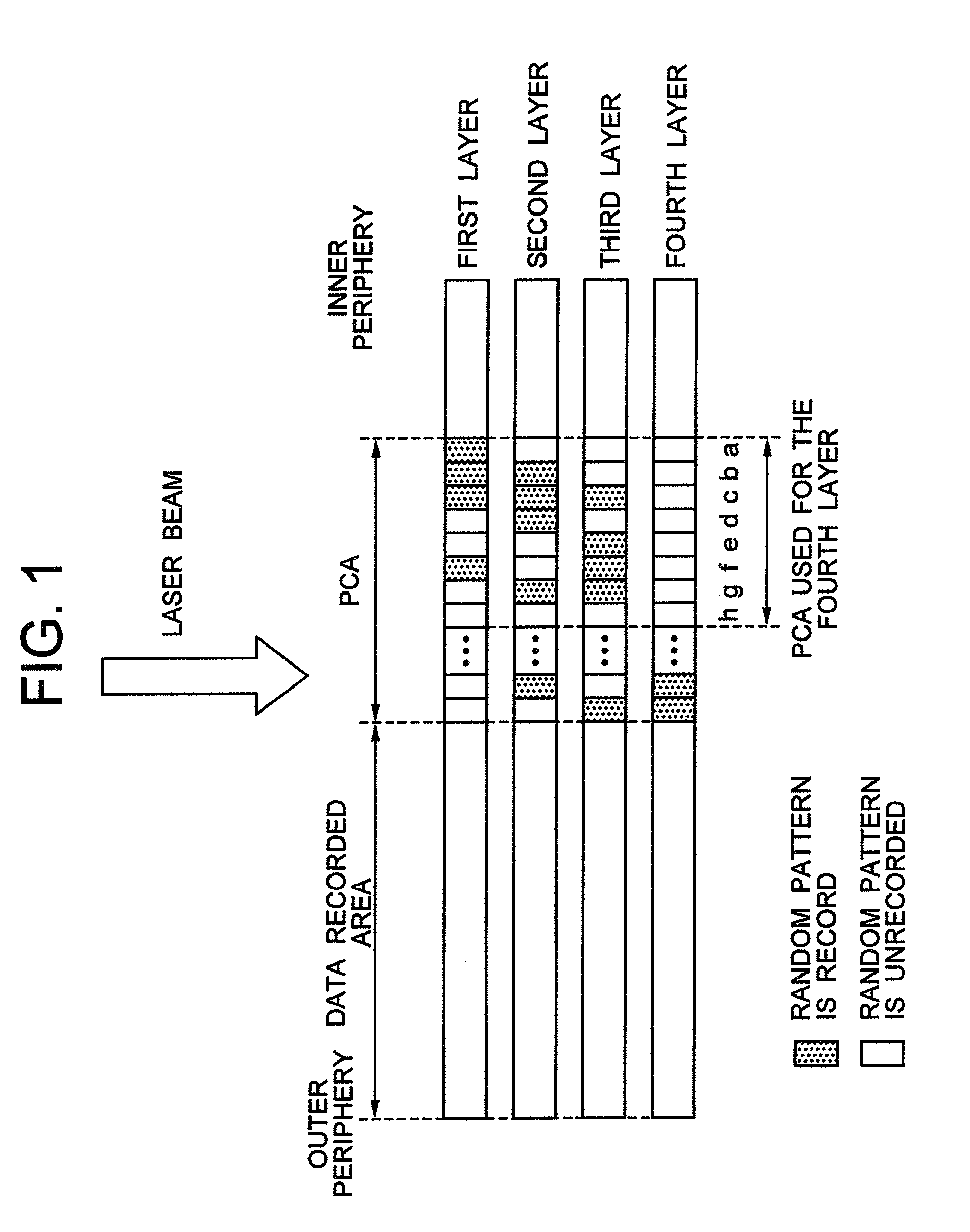
[0016]FIG. 1 is a cross sectional view of a multi-layer optical disc, which is recordable or reproducible from one side, where the right side is an inner peripheral side of the optical disc and the left side is an outer peripheral side of the optical disc. A laser beam for recording into or reproducing from each layer of this optical disc is incident from the above. Hereinafter, these layers are referred to as a first layer, a second layer, a third layer, and a fourth layer in this order from the one nearest to the incident plane of the laser beam.

[0017] Each layer has, as the recordable areas, a test writing area PCA (Power Calibration Area) where OPC is carried out to calculate an optimum power, and a data recording area to which a user data is written. Namely, in FIG. 1, there are four PCAs: the PCA for th...

third embodiment

[0050] In Step 306, as in the third embodiment, the calculated average value is registered as the optimum recording power of the m-th layer.

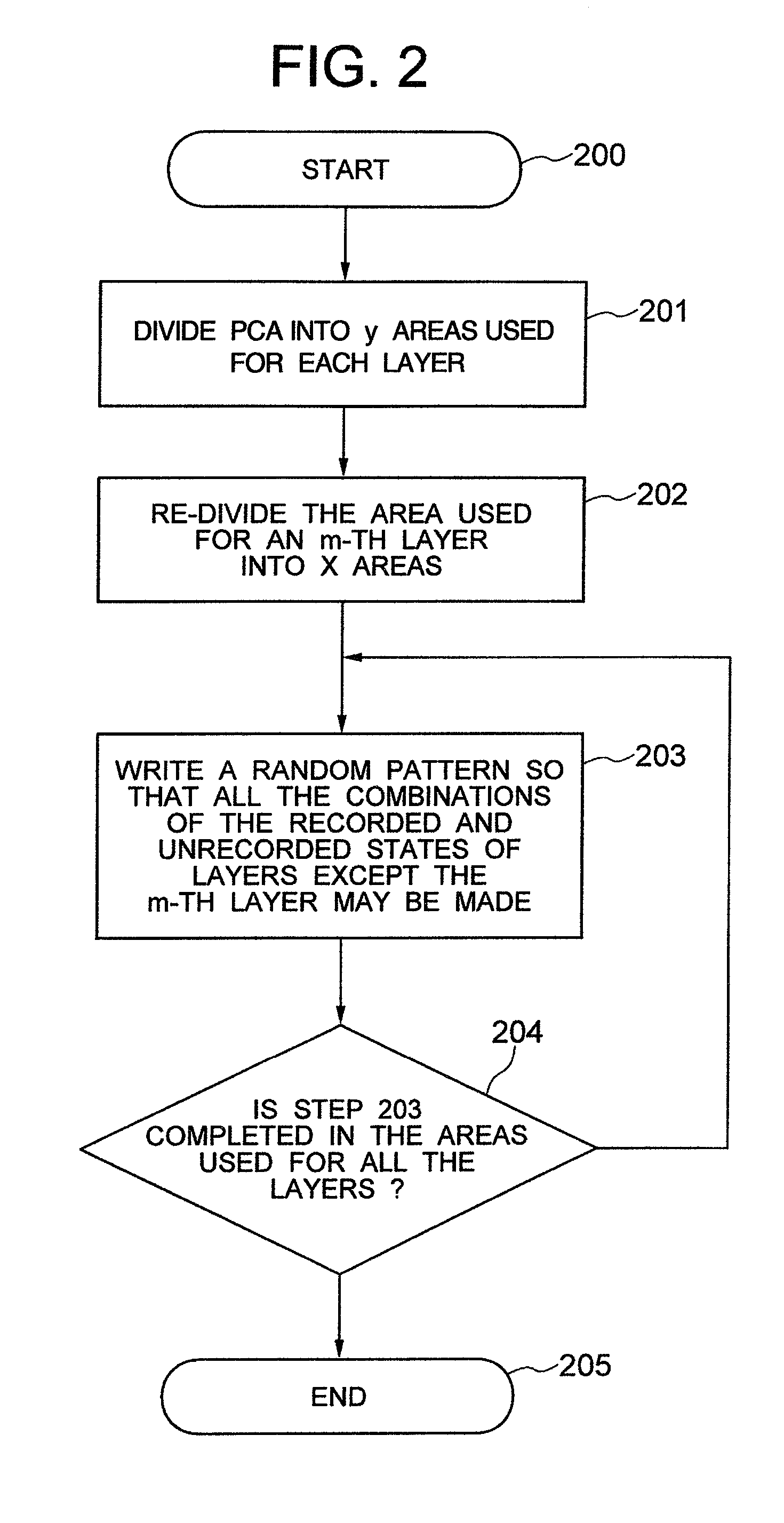
[0051] As described above, according to this embodiment, even if a random access, including the random access between the layers, is allowed in a multi-layer optical disc, the optimum recording power can be calculated. In addition, although in this embodiment the OPC of the m-th layer has been described, the same is true of other layer. Moreover, also in this embodiment, with respect to the PCA used for the m-th layer, all the combinations of the recorded and unrecorded states of the other layers are provided to carry out OPC, however, as in the third embodiment, with respect to the PCA used for the m-th layer, all the combinations of the recorded and unrecorded states of the upper layers or a combination of areas selectively selected may be provided to carry out OPC. Moreover, it is also possible to carry out OPC only to an area having the maxi...

fifth embodiment

[0052]FIG. 5 is a block diagram showing a fifth embodiment that is a recording apparatus for the multi-layer optical disc of the present invention.

[0053] In FIG. 5, reference numeral 501 represents an optical disc, reference numeral 502 represents a disc motor for rotating the optical disc 501, reference numeral 503 represents a laser that emits light for reading from and writing to the optical disc 501, reference numeral 504 represents an optical pickup having the laser 503 and further having a lens for focusing the laser beam on the optical disc, and an OEIC (optical electronic IC) for converting an optical signal into an electric signal, and reference numeral 505 represents a signal reproduction processing circuit, which carries out waveform equalization to a signal detected in the optical pickup 504, and reproduces a synchronous clock. The signal reproduction processing circuit further detects jitter at each edge.

[0054] Reference numeral 506 represents a test-write reproduction...


PUM

PropertyMeasurementUnit
areaaaaaaaaaaa
areasaaaaaaaaaa
recording poweraaaaaaaaaa

Abstract

Each layer includes a data recording area and a test writing area divided into a plurality of small areas, wherein the small areas of the test writing area are recorded in advance so that other each layer can make a combination of recorded and unrecorded states with respect to the small area, where OPC is carried out, in a layer where OPC is carried out. Moreover, OPC is carried out to each small area, where a combination of recorded/unrecorded states of other each layer differs from each other, to thereby calculate, as the optimum power, an average value of the result of each OPC or a central value of the dispersion thereof.

Description

INCORPORATION BY REFERENCE [0001] The present application claims priority from Japanese application JP2006-291968 filed on Oct. 27, 2006, the content of which is hereby incorporated by reference into this application. BACKGROUND OF THE INVENTION [0002] The present invention relates to multi-layer optical discs, and in particular relates to a method of calculating an optimum value of a laser power for recording into a multi-layer optical disc. [0003] In the case where information is recorded into an optical disc having an once-writable or rewritable multi-layer structure, a method of JP-A-2000-311346 is known as the method of adjusting the laser output during recording to an optimum recording power value with respect to a data area of a layer, to which information is written (Optimum Power Control, hereinafter, referred to as “OPC”). SUMMARY OF THE INVENTION [0004] When recording information by irradiating a multi-layer optical disc with a laser beam, a difference will arise in the t...

Claims


Application Information

Patent Timeline
Patent Type & Authority Applications(United States)
IPC IPC(8): G11B7/26
CPCG11B7/1267G11B2007/0009G11B7/24038G11B7/007G11B7/24073
Inventor NAGAI, YUTAKANISHIMURA, KOICHIRO
Owner HITACHI CONSUMER ELECTRONICS CORP
Why Eureka
Try Eureka