
Multiple Phase State Near-Field Electromagnetic System And Method For Communication And Location

a near-field electromagnetic system and multi-phase technology, applied in the field of near-field electromagnetic systems, can solve the problems of multi-path limit the utility of wireless systems, cluttered environment, and difficult operation of conventional wireless systems in complex environments

Inactive Publication Date: 2009-11-12
Q TRACK CORP
View PDF1 Cites 30 Cited by
  • Summary
  • Abstract
  • Description
  • Claims
  • Application Information

AI Technical Summary

Benefits of technology

[0014]The present invention will now be described more fully in detail with reference to the accompanying drawings, in which the preferred embodiments of the invention are shown. This invention should not, however, be construed as limited t

Problems solved by technology

Conventional wireless systems have difficulty operating in complicated, cluttered, environments.
Multipath tends to scramble data communications and confound location systems.
Multipath limits the utility of wireless systems in dangerous environments where robust data links and reliable location information are most essential.
Any number of industrial accidents have been made far worse because rescuers were unable to locate injured workers, delaying rescue and risking the rescuers' own safety by prolonged searching.
Each of these applications often involves indoor or urban canyon environments were GPS is unavailable or operates poorly or has insufficient accuracy to pinpoint an object location to a particular room, shelf or bin.

Method used


Image

  • Multiple Phase State Near-Field Electromagnetic System And Method For Communication And Location
  • Multiple Phase State Near-Field Electromagnetic System And Method For Communication And Location
  • Multiple Phase State Near-Field Electromagnetic System And Method For Communication And Location

Examples


Embodiment Construction

Overview of the Invention

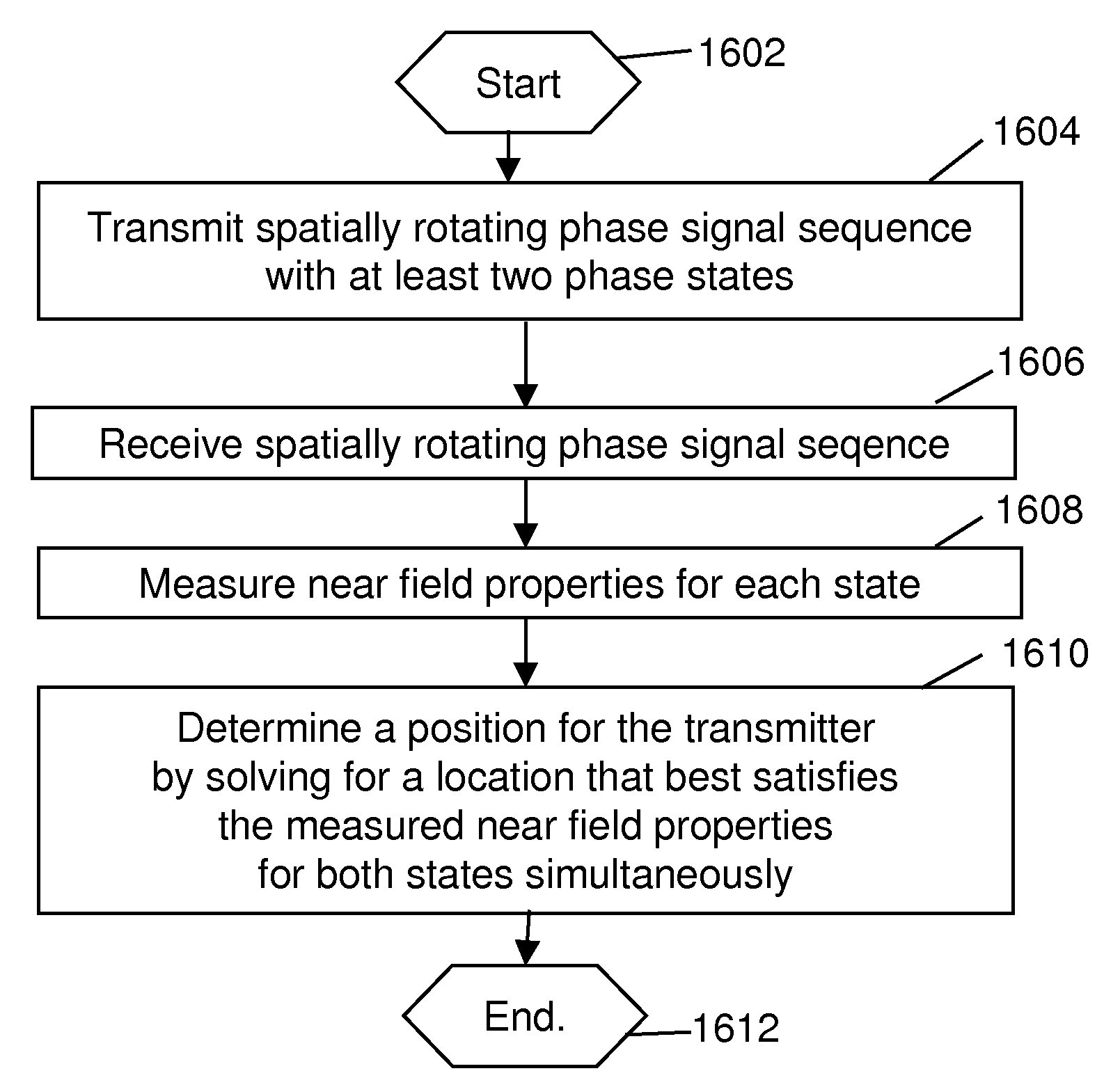
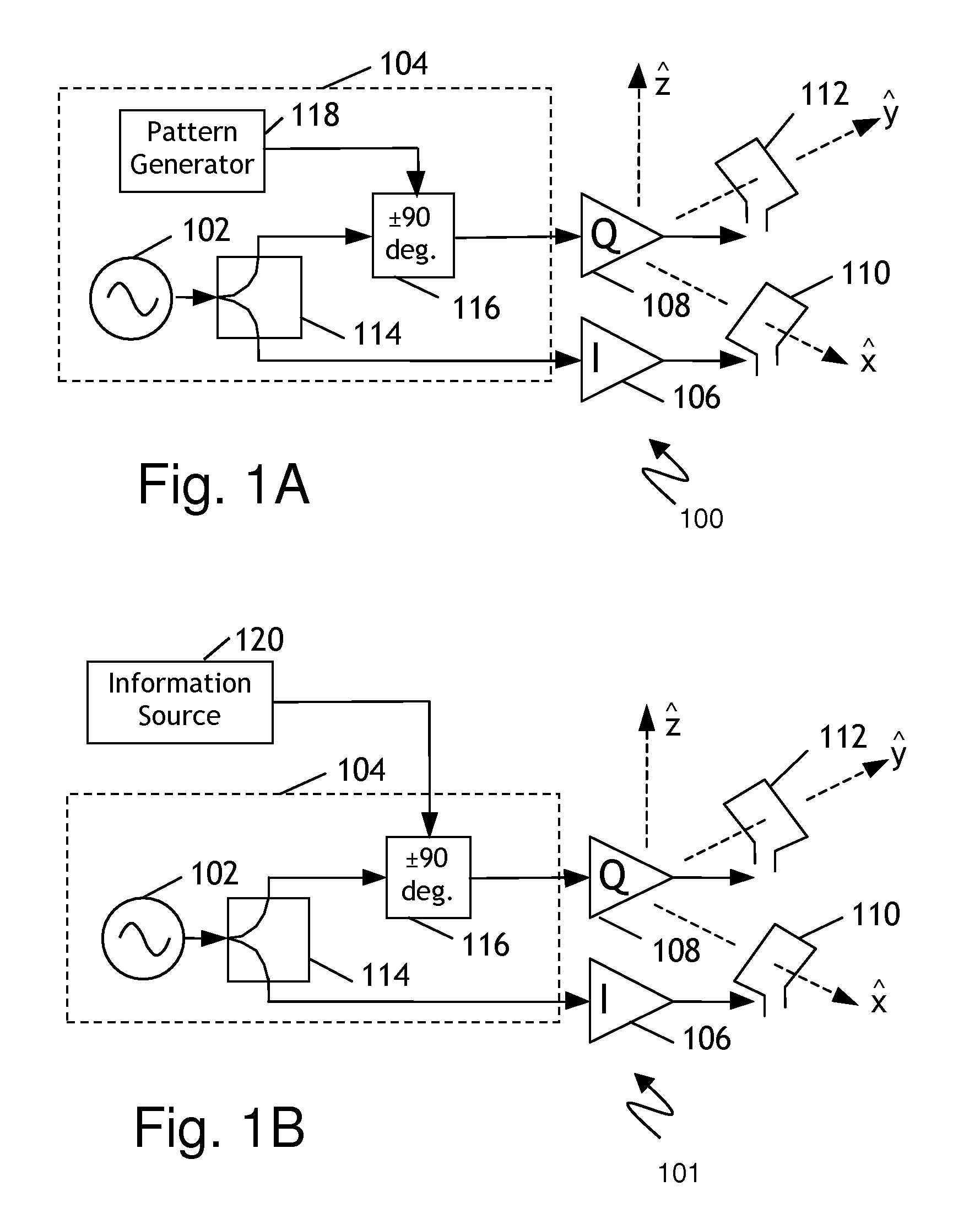
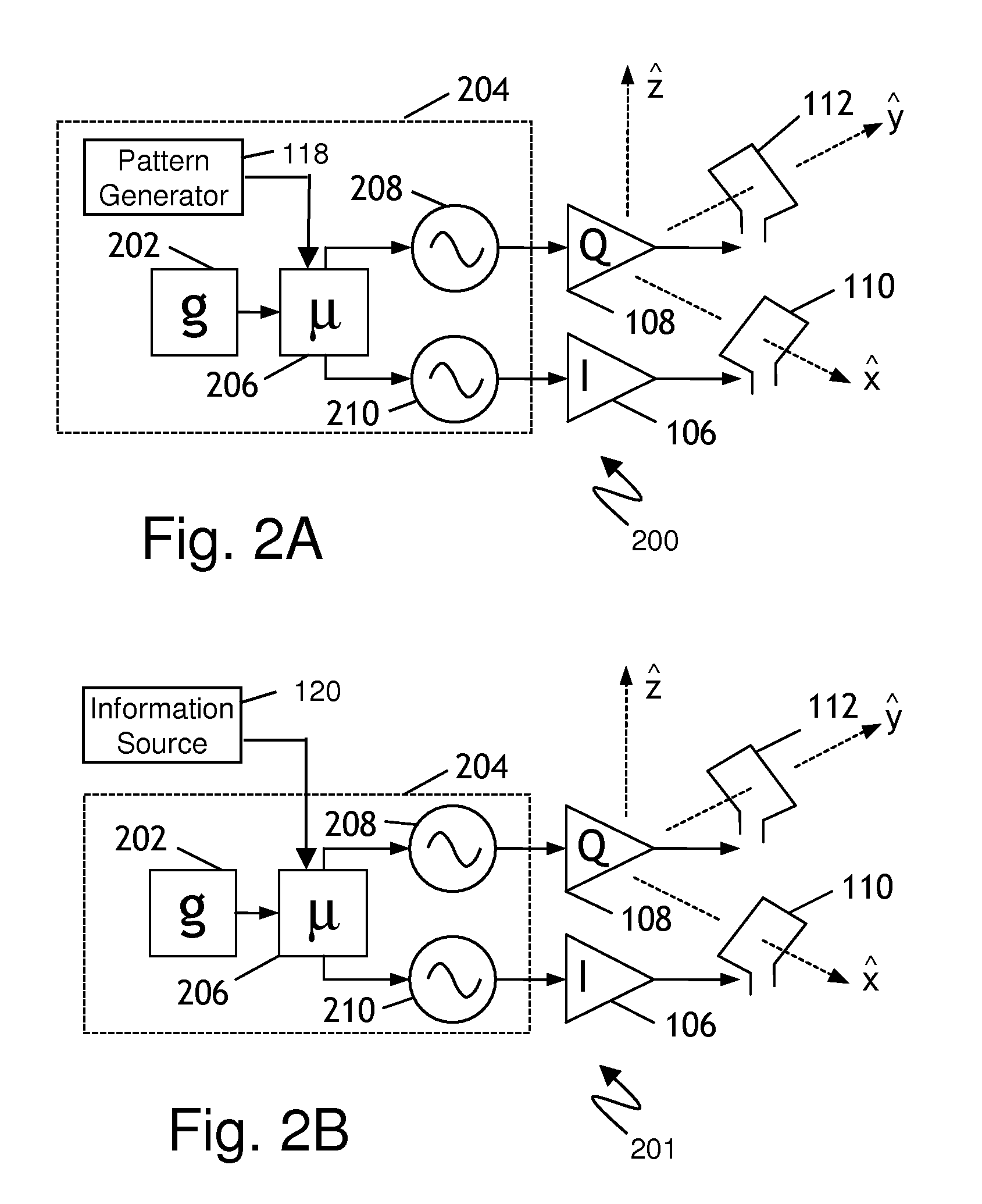
[0033]The present invention is directed to a multiple phase state near-field electromagnetic system and method of communication and location. The system is based on establishing a plurality of near-field phase states in the vicinity of the transmitter. In a preferred embodiment, a rotating pattern yields a spiral phase state near field signal, which may be generated by feeding two orthogonal H-field antennas with two respective signals 90 degrees out of phase. A unique property of the resulting transmitted signal is that the phase relationship between the E-field and H-field, as a function of distance and orientation from the antennas, generates a spiral pattern of equal phase solutions indicative of distance and direction. The spiral pattern quickly becomes asymptotic with distance and is not noticeable in the far field signals. These spiral patterns are described in greater detail later with reference to FIG. 6A-6F. When the direction of pattern rotation i...


PUM


Abstract

A multiple phase state near-field electromagnetic location and communication system includes a multiple phase state near-field transmitter, and a near-field locator receiver. The near-field transmitter is capable of operation in at least two states and each of these at least two states generates a state characteristic difference detected at the near-field locator receiver. The state characteristic difference may be employed for location determination, communication or both. The present invention is particularly well-suited for use in conjunction with a near-field electromagnetic ranging system. In further embodiments, a multiple phase state near-field electromagnetic location and communication process includes the steps of determining a transmission state for a near-field quadrature transmitter, transmitting a near-field transmission corresponding to said transmission state, receiving a near-field transmission corresponding to said transmission state, and determining a difference between at least two properties of said near-field transmission where the difference is characteristic of and corresponding to the transmission state.

Description

[0001]This application claims the benefit under 35 U.S.C. 119(e) of U.S. Provisional Application 61 / 067,002, titled “State variable near-field electromagnetic system and method for communication and location,” filed Feb. 25, 2008 by Schantz et al.RELATED APPLICATIONS AND GOVERNMENT RIGHTS[0002]The U.S. Government has a paid up license in this invention and the right in limited circumstances to require the patent owner to license others on reasonable terms as provided for by the terms of Grant 1R43OH008952-01A1 awarded by NIOSH and US Army Contract W15P7T-07-C-M007.FIELD OF THE INVENTION[0003]The present invention relates generally to near-field electromagnetic systems, particularly for use in measurement of position or location by means of electromagnetic signaling, as well as for communication.BACKGROUND[0004]Conventional wireless systems have difficulty operating in complicated, cluttered, environments. This is because their high frequency links suffer from “multipath.” Multipath ...

Claims


Application Information

Patent Timeline
IPC IPC(8): H04B5/00
CPCH04B5/02H04B5/48H04W64/00H04W72/12
Inventor SCHANTZ, HANS GREGORYCOMPSTON, ANDREWDEPIERRE, ROBERTBARRON, JAMES MATTHEW
Owner Q TRACK CORP
Learn More