Bio-mechanical sensor system

a sensor system and biomechanical technology, applied in the field of biomechanical sensor systems, can solve the problems of inconvenient portability, inconvenient wear, and inconvenient use of physiological monitoring systems,

a sensor system and biomechanical technology, applied in the field of biomechanical sensor systems, can solve the problems of inconvenient portability, inconvenient wear, and inconvenient use of physiological monitoring systems,

US20090281394A1Inactive Publication Date: 2009-11-12ZEPHYR TECH CORP

Image

  • Bio-mechanical sensor system
  • Bio-mechanical sensor system
  • Bio-mechanical sensor system

Examples


Embodiment Construction

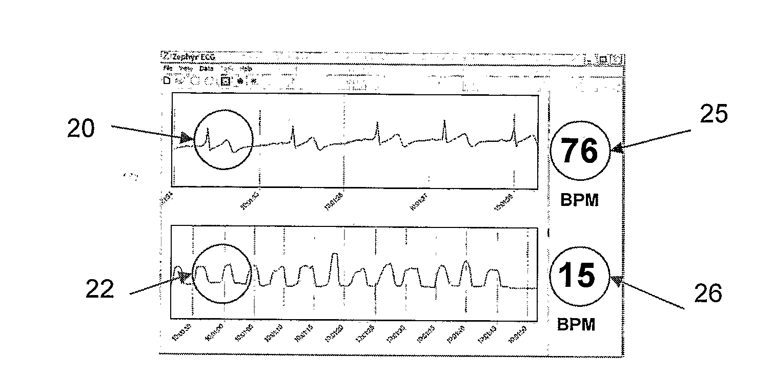
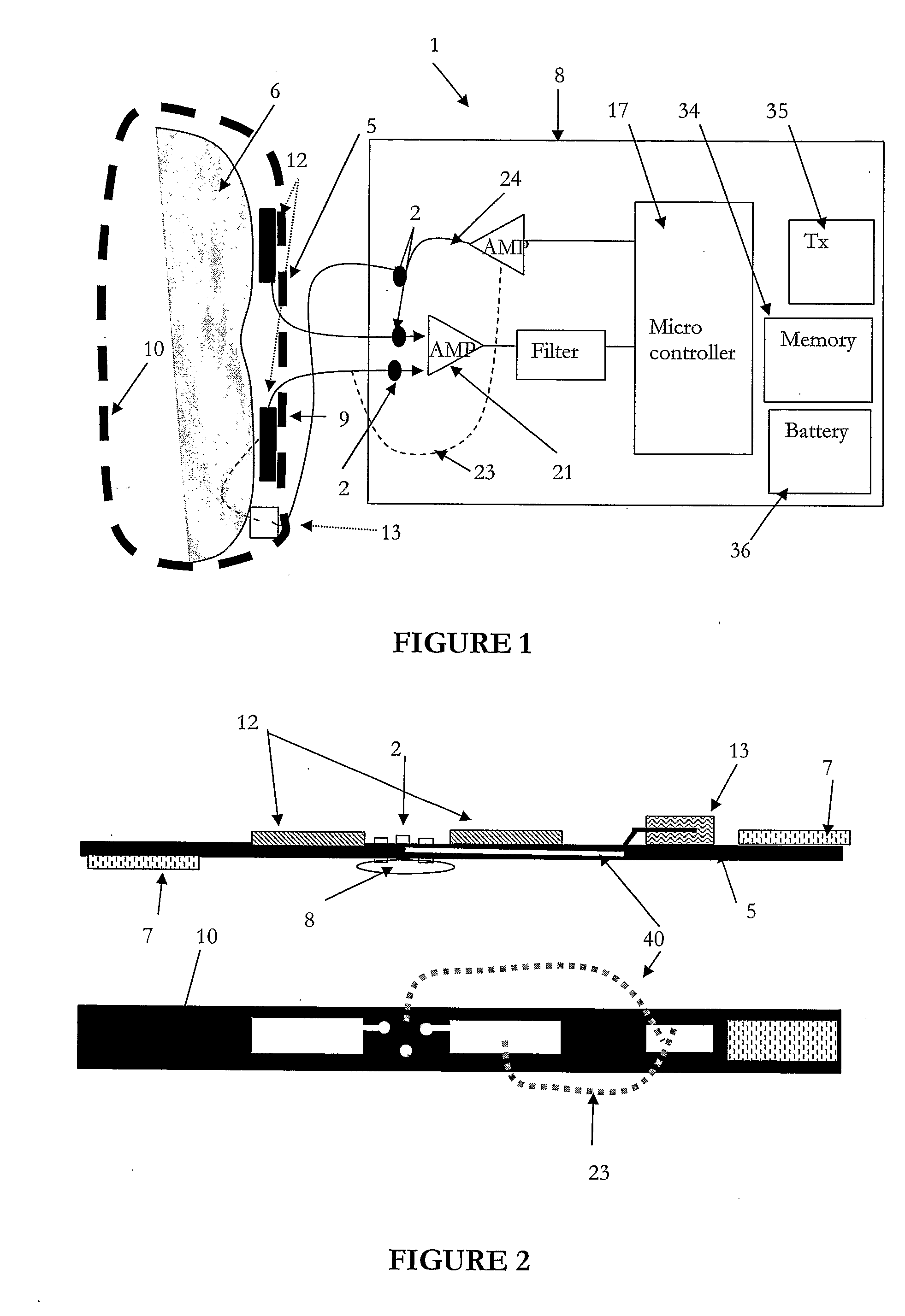
[0097]The bio mechanical sensor system of the present invention can be used in ambulatory monitoring, emergency room situations, in the home or even be used whilst exercising. The system provides a means of sensing, monitoring and recording an individual's physiological parameters such as their heart rate, respiration rate, ambient temperature and body temperature using a wearable garment such as a single body harness or strap attached to the individual. The list of sensor types that can be incorporated into the body harness may also include non-physiological sensors such as pressure sensors for sensing altitude changes, a flux gate compass for sensing an individual's direction of travel or an accelerometer to measure angle of orientation and activity. Whilst a number of sensing mechanisms have been mentioned these are in no way limiting as the sensing system can be used in a wide variety of environments and for a wide variety of purposes.

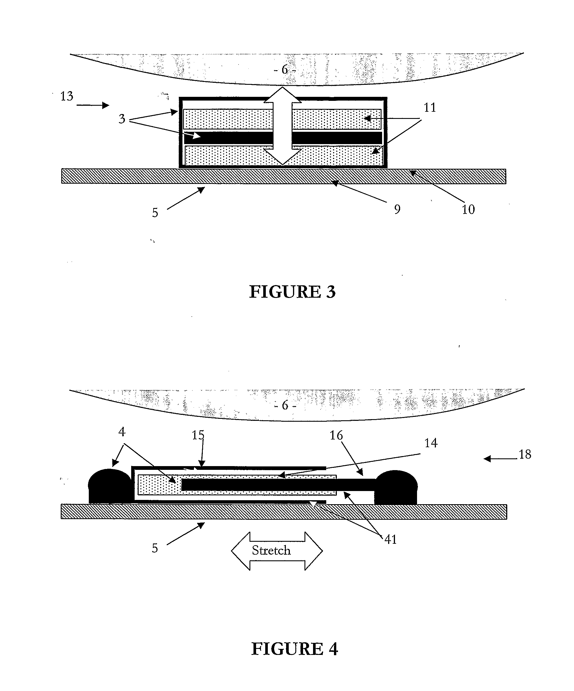
Conductive Fabric Sensors

[0098]A preferred e...


PUM


Abstract

The bio mechanical sensor system is disclosed that uses conductive fabric sensors to detect, monitor and record one or more physiological parameters of a person wearing a garment that incorporates the fabric sensors such as a body harness or strap for example, that is attached to a person. The physiological parameters that can be detected include a wearer's heart rate and respiration rate plus ambient temperature and body temperature for example. The garment has a monitoring device that is attached to the garment and used to receive the detected physiological data. A processing circuit within the monitoring device then processes the data and outputs the person's physiological data to a display device in a format characteristic of the person's heart rate and respiratory rate and / or outputs the data to a third party system for review and analysis.

Description

TECHNICAL FIELD[0001]The present invention relates to a system and method for monitoring multiple bio mechanical parameters of an individual. More particularly, the present invention relates to a personal bio mechanical harness system that uses conductive fabric sensors to detect a number physiological parameters for review and / or analysis using a third party system.BACKGROUND ART[0002]The monitoring of an individual's physiological parameters is a routine process in clinics and hospitals. Such monitoring generally requires the individual to lie down and have a number of adhesive type patches attached to a patient's chest area for example. Each of the patches are connected to monitoring equipment using electrical cables or leads enabling the individual's physiological parameters to be monitored, recorded and analysed for diagnostic purposes. It is generally preferable to attach up to 12 patches and associated leads to the individual in order to monitor and assess a patient's conditi...

Claims


Application Information

Patent Timeline
12 Nov 2009
Publication
US20090281394A1
IPC
A61B5/00; A61B5/04
CPC
A61B5/0002; A61B5/0205; A61B5/6805; A61B5/0816; A61B5/6804; A61B5/02438
Inventors
RUSSELL, BRIAN KEITH; KENT, STEPHEN CHRISTOPHER