
Negative Pressure Wound Therapy Apparatus Including a Fluid Line Coupling

Inactive Publication Date: 2009-11-12
TYCO HEALTHCARE GRP LP
View PDF64 Cites 83 Cited by
  • Summary
  • Abstract
  • Description
  • Claims
  • Application Information

AI Technical Summary

Benefits of technology

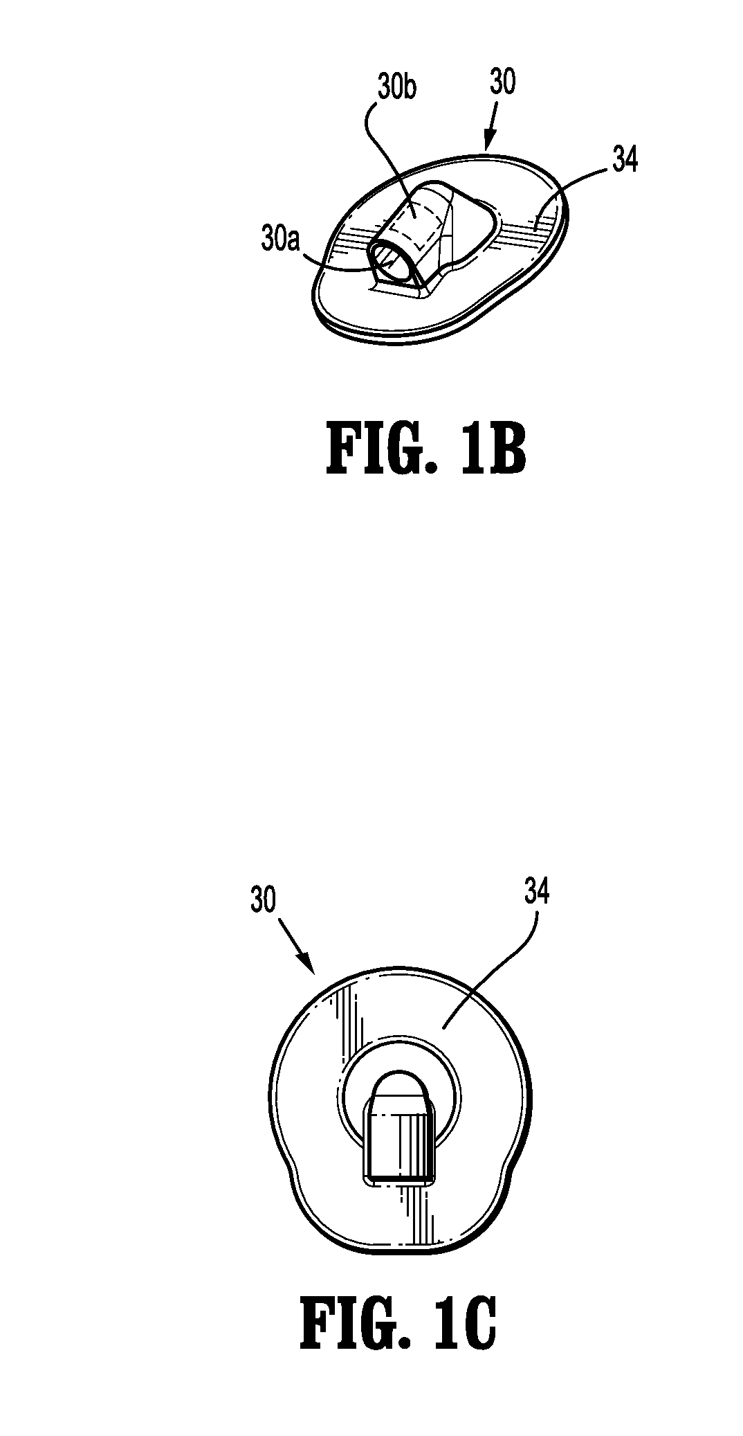
[0020]A fluid portal flange may be mounted to the wound cover and adapted to couple to the fluid conduit. The fluid portal flange defines a portal opening in fluid communication with the reservoir. The fluid portal flange may include at least a flange segment having one of translucent or opaque characteristics to prevent direct visualization of exudates passing through the fluid portal flange.

Problems solved by technology

Because fluids may continue to flow through the fluid conduit throughout an NPWT treatment, changing the canister may reduce the effectiveness of the treatment by requiring an interruption in the treatment.
Unfortunately, the exudates removed from the wound may be offensive both visually and with respect to smell.
This may prove troublesome with an ambulatory system for wound therapy where the removed exudates may be viewed in the tubing or collection canister.

Method used


Image

  • Negative Pressure Wound Therapy Apparatus Including a Fluid Line Coupling
  • Negative Pressure Wound Therapy Apparatus Including a Fluid Line Coupling
  • Negative Pressure Wound Therapy Apparatus Including a Fluid Line Coupling

Examples


second embodiment

[0077]Referring now to FIG. 3A, a fluid line coupling is depicted generally as 200 arranged in an engaged and locked configuration to fluidly couple first and second conduit portions 44, 46. Coupling 200 includes first and second coupling segments 202, 204 each receiving a respective one of the first and second conduit sections 44, 46 therein. Coupling segments 202, 204 are each tapered at one end to provide a gripping surface 206, which may be positioned between a thumb and a forefinger of an operator to facilitate engagement and disengagement of the coupling segments 202, 204. Gripping surfaces 206 are textured and extend laterally to assume a disk shape. This shape assists an operator in generating a torque between the coupling segments 202, 204 to allow the coupling segments 202, 204 to twist relative to one another to permit the engagement and disengagement of the coupling segments 202, 204. When the two coupling segments 202, 204 are properly engaged as depicted in FIG. 3A, fl...

third embodiment

[0079]Referring now to FIG. 4A, a fluid line coupling is depicted generally as 300 arranged in an engaged and locked configuration to fluidly couple first and second conduit sections 144, 146. Fluid conduit sections 144, 146 have a broader cross section than fluid conduit sections 44 and 46 to accommodate side-by-side flow channels. A multi-lumen conduit such as 144, 146 may be used in an NPWT apparatus to provide a redundancy such that fluid may flow through the conduit section 144, 146 even in the event one of the lumens becomes occluded. The occlusion of a lumen may occur, for example, as wound exudates are deposited on the interior walls of fluid conduit sections 144, 146 and accumulate until fluid flow is restricted.

[0080]Coupling 300 includes first and second coupling segments 302, 304 each receiving a respective one of the first and second conduit sections 144, 146 therein. Coupling segments 302, 304 each provide a number of depressed gripping surfaces 306 to facilitate handl...

fourth embodiment

[0084]Referring now to FIG. 5A, a fluid line coupling is depicted generally as 400 in a disengaged configuration. Coupling 400 includes first and second coupling segments 402, 404 each receiving a respective one of the first and second conduit sections 44, 46 therein. Coupling segments 402, 404 each provide a gripping component 406, 408 respectively, which may facilitate handling by an operator to engage and disengage first and second coupling segments 402, 404. When the two coupling segments 402, 404 are disengaged, fluid flow is restricted through first and second conduit sections 44, 46, but when coupling segments 402, 404 are properly engaged, fluids may pass freely between first and second conduit sections 44, 46. A locking nut 410 provides a locking mechanism for fluid line coupling 400. Locking nut 410 is positioned loosely around gripping component 406 of first coupling segment 402 such that it may rotate freely thereabout. Exterior threads 412 on gripping component 408 of s...


PUM


Abstract

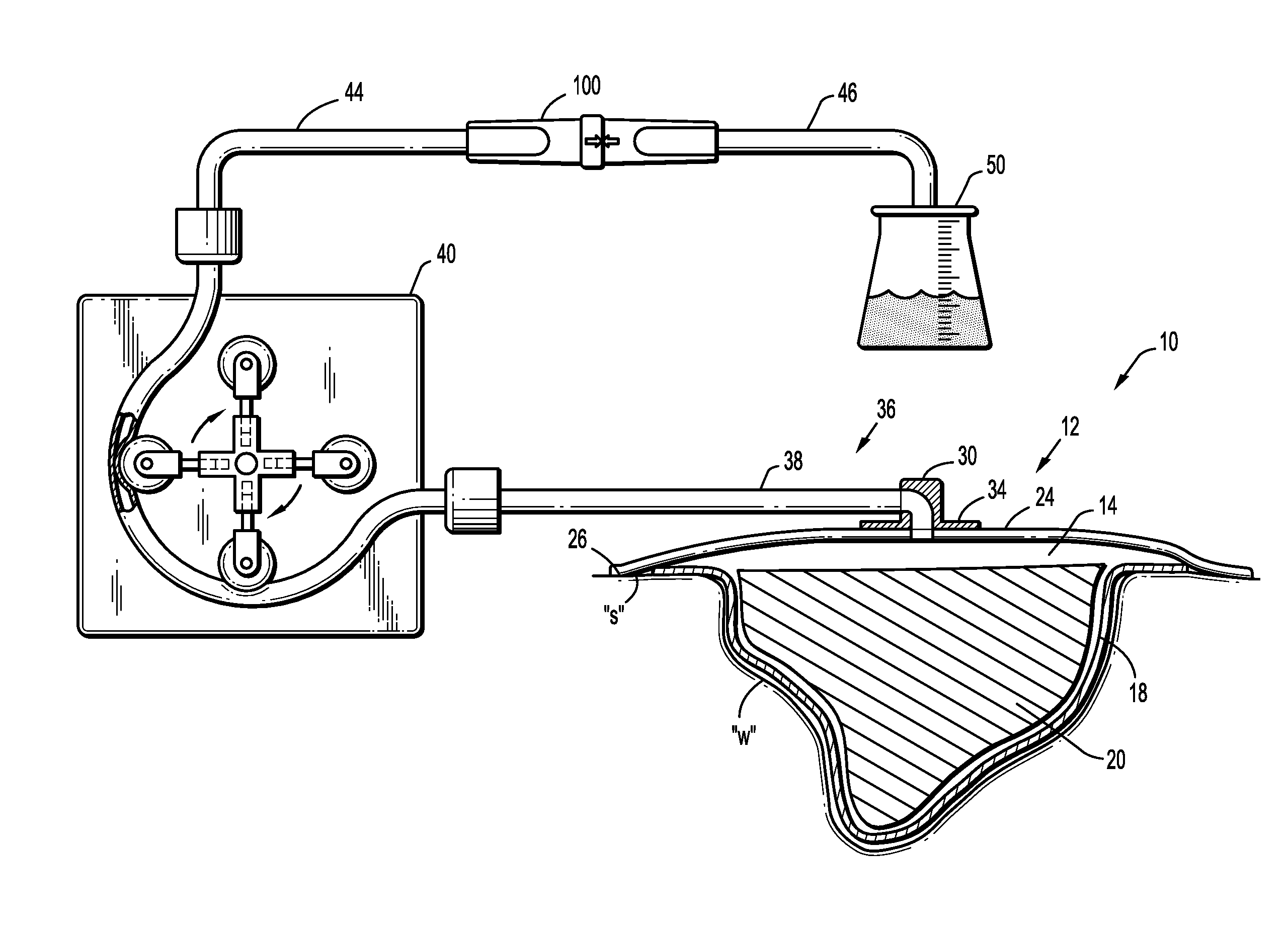
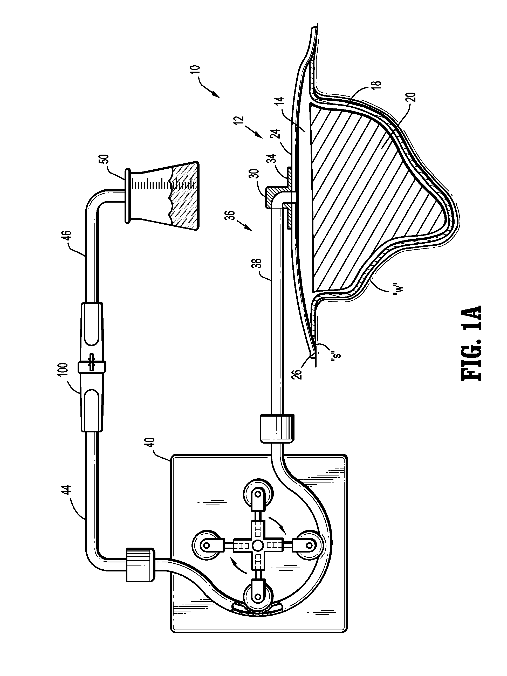
A negative pressure wound therapy apparatus includes a wound dressing for forming a substantially fluid-tight seal over a wound to define a reservoir over the wound in which a negative pressure may be maintained. A vacuum source is in fluid communication with the reservoir to provide an appropriate negative pressure to the reservoir to stimulate healing of the wound. The apparatus includes a fluid conduit in fluid communication with the reservoir and defining a fluid flow path for carrying fluids from the reservoir, and a fluid line coupling adapted for selective engagement and disengagement of first and second coupling segments to respectively maintain and interrupt the fluid flow path.

Description

CROSS-REFERENCE TO RELATED APPLICATIONS[0001]This application claims priority to, and the benefit of, U.S. Provisional Patent Application No. 61 / 051,825, filed on May 9, 2008 and U.S. Provisional Patent Application No. 61 / 094,527, filed on Sep. 5, 2008, the entire contents of which are incorporated herein by reference.BACKGROUND[0002]1. Technical Field[0003]The present disclosure relates generally to an apparatus for stimulating healing of a wound by applying a reduced pressure over the wound. In particular, the disclosure relates to an apparatus including a fluid line coupling to facilitate disconnection of apparatus components.[0004]2. Background of Related Art[0005]One technique that has proven effective in promoting the healing of wounds is known as negative pressure wound therapy (NPWT). Application of a negative pressure, e.g. reduced or sub-atmospheric pressure, to a localized reservoir over a wound has been found to assist in closing the wound by promoting blood flow to the ...

Claims


Application Information

Patent Timeline
IPC IPC(8): A61M27/00
CPCA61M1/0088A61M27/00A61M39/1011A61M1/0086A61M39/284A61M2039/1044A61M1/0031A61M39/26A61M1/86A61M1/982A61M1/915A61M1/984A61M1/74
Inventor KENNY, GREGORYDEPIANO, JR., JOHNCARLYON, JAMES L.FINK, DAVID E.BRAGA, RICHARD M.
Owner TYCO HEALTHCARE GRP LP
Learn More