Method and device for assemblying torsion box structures for an aircraft

a torsion box and aircraft technology, applied in the field of aircraft structures, can solve the problems of inability to accurately measure the aerodynamic surface of the skin, increase the cost of the assembly method, and complex positioning system of the ribs (stops or templates), and achieve the effect of eliminating unnecessary assembly operations and simplifying the assembly method

Inactive Publication Date: 2009-11-19
AIRBUS OPERATIONS SL
View PDF6 Cites 39 Cited by
  • Summary
  • Abstract
  • Description
  • Claims
  • Application Information

AI Technical Summary

Benefits of technology

[0001]As stated in the title of this descriptive specification, the present invention has the aim of providing a method for assembly of a torsion box type structure for aeronautical use ensuring certain minimum dimensional tolerances in the aerodynamic outer surface of the skin, simplifying the assembly method and eliminating unnecessary assembly operations.

Problems solved by technology

This can be due to manufacturing errors such as deviations in the angle of opening of the flanges or deviations in the thickness of the skin, though it is mainly due to assembly errors on account of imprecise positioning of the rib, above all as a consequence of the intrinsic inaccuracy of the system of positioning the ribs based on the use of the said stops or templates.
These adjustment operations present the drawback that they are very laborious and therefore considerably increase the cost of the assembly method.
As has been seen, some of the drawbacks shown by the conventional method for assembly of torsion boxes are: inaccuracy of the aerodynamic surface of the skin following the assembly; the complexity of the positioning system for the ribs (stops or templates); and the carrying out of laborious adjustment operations.

Method used


Image

  • Method and device for assemblying torsion box structures for an aircraft
  • Method and device for assemblying torsion box structures for an aircraft
  • Method and device for assemblying torsion box structures for an aircraft

Examples


Embodiment Construction

[0024]The method proposed in the present invention aims to avoid the drawbacks stated above, permitting torsion boxes to be obtained that are more accurate in the aerodynamic surface of the skin, simplifying the assembly and eliminating unnecessary adjustment operations, thereby achieving a reduction in cost and an improvement in the performance of the torsion boxes produced.

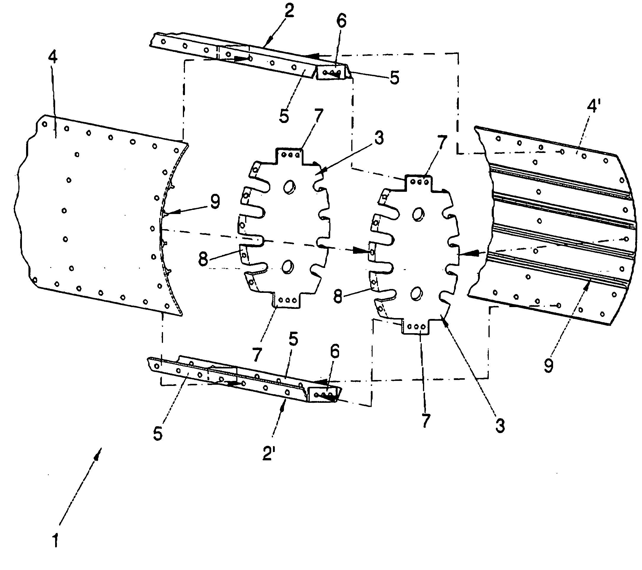
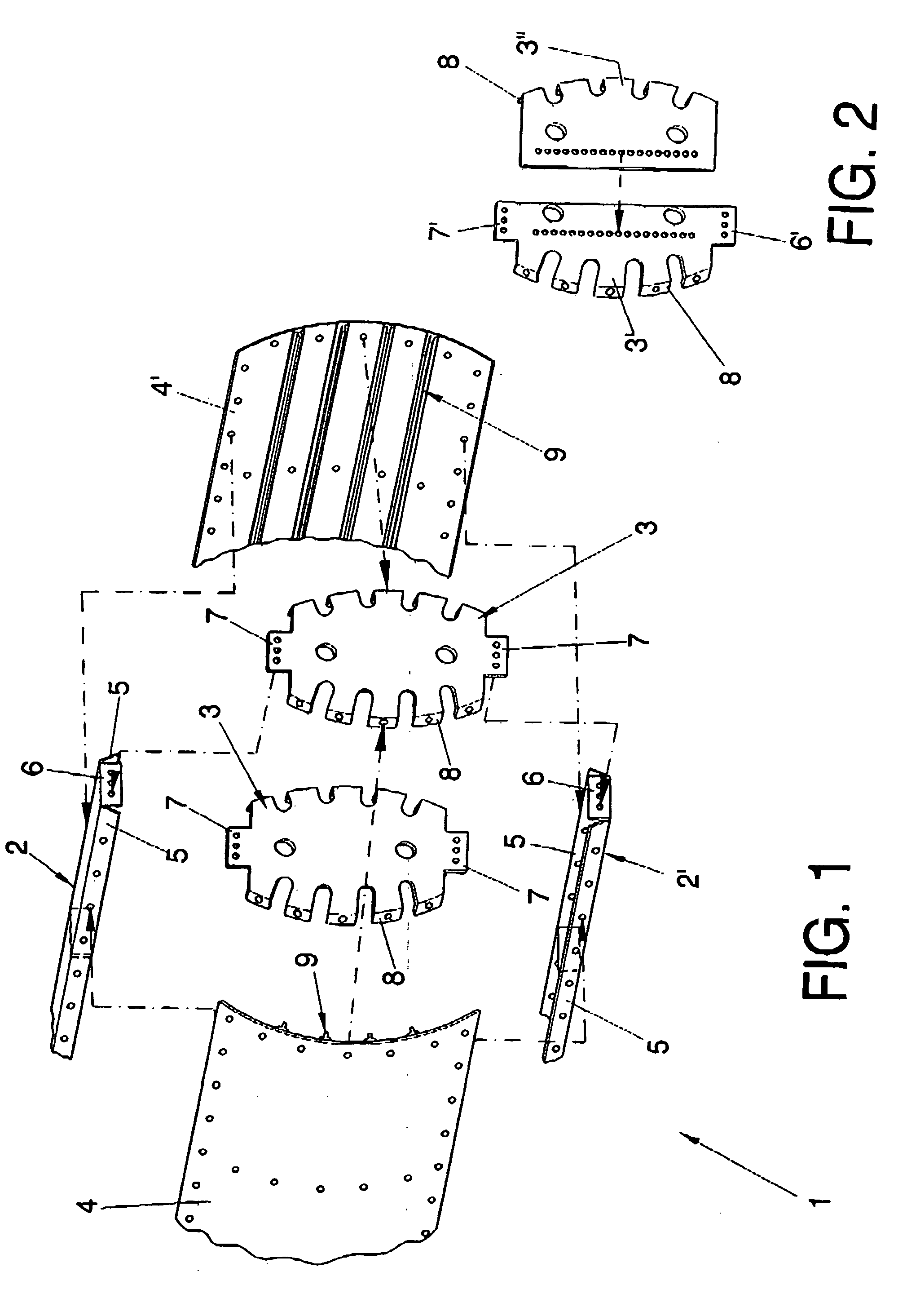
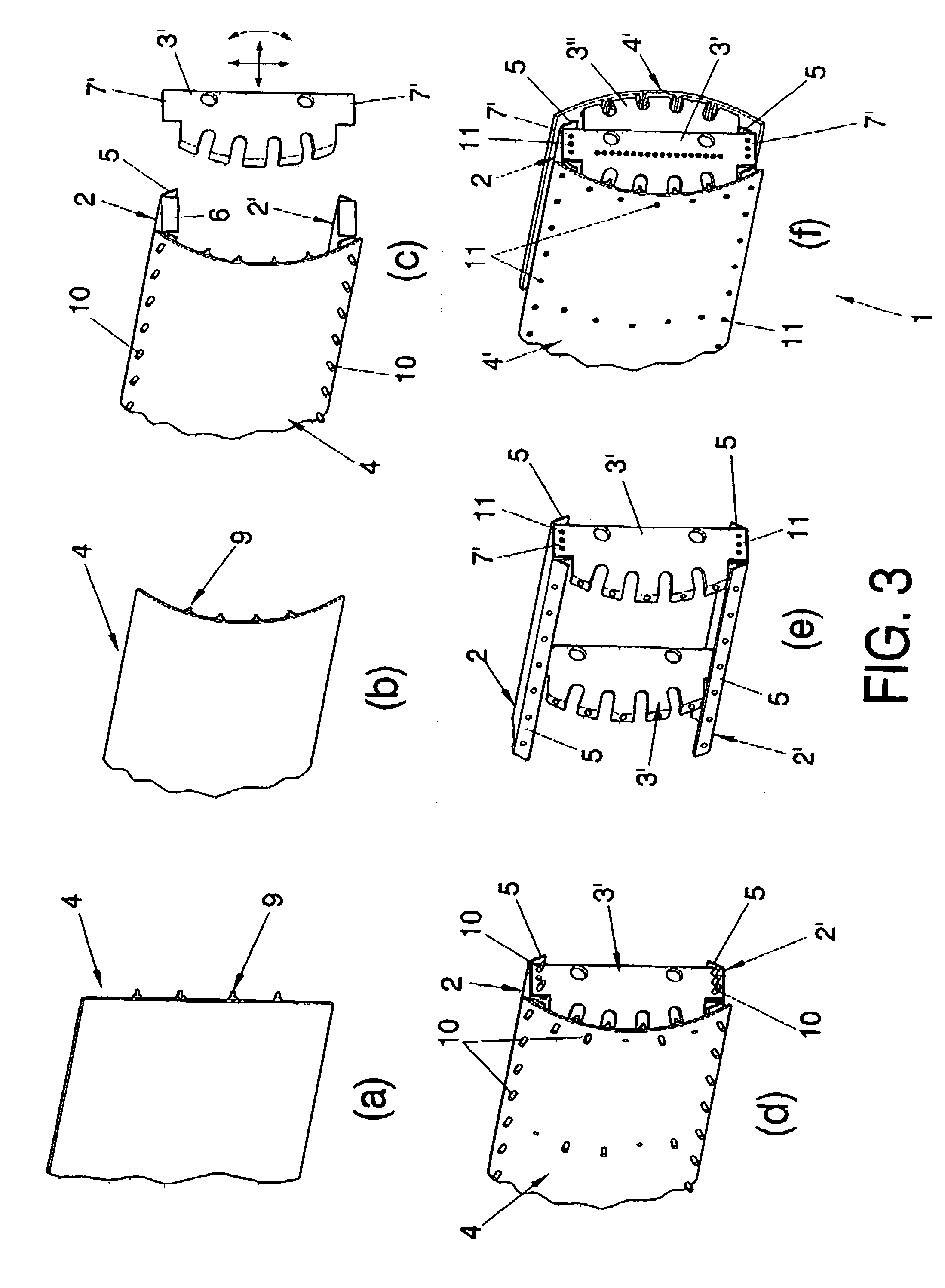
[0025]The assembly method for torsion boxes for aeronautical use of the present invention basically consists of assembling the skeleton of the torsion box (spars and ribs) simultaneously with the skin, in such a way that the ribs are positioned with reference to the skin, being temporarily fixed to the latter once positioned, rather than to the spars.

[0026]The skin of the torsion boxes for aeronautical use has the nature of being flaccid, flaccid being understood as the fact that the skin, prior to being assembled on the skeleton of the structure, does not per se have the form that it acquires once assembled, in...


PUM

PropertyMeasurementUnit
shapeaaaaaaaaaa
structureaaaaaaaaaa
internal tensionaaaaaaaaaa

Abstract

The method basically consists of mounting the spars (2, 2′) and the ribs (3) with reference to the skin (4) in such a manner that, once the spars (2, 2′) are positioned with their proper reference in an assembly jig (12), the ribs (3) are transversely positioned with the condition that they are adjusted making contact against the inner surface of the skin (4).The device comprises a template element (15) which is used for previously providing the skin with the theoretical form it must acquire once mounted, and to firmly maintain that theoretical form by including means for securing and tightening (16) the skin (4), as well as means (17, 18, 19, 20) for supporting and positioning the skin (4).

Description

OBJECT OF THE INVENTION[0001]As stated in the title of this descriptive specification, the present invention has the aim of providing a method for assembly of a torsion box type structure for aeronautical use ensuring certain minimum dimensional tolerances in the aerodynamic outer surface of the skin, simplifying the assembly method and eliminating unnecessary assembly operations.TECHNICAL FIELD OF THE INVENTION[0002]As revealed in the previous section, the present invention has application in the aeronautical industry, in the technical field of aircraft structures, particularly torsion box type structures.[0003]Torsion box type structures, simply named as torsion boxes, whose assembly method this invention refers to, are structures well known in the technical field of aircraft structures. So, torsion boxes currently constitute the main structural element of the wings and the horizontal tail plane in aircraft.[0004]A torsion box is essentially defined as a structure consisting of: s...

Claims


Application Information

Patent Timeline
Patent Type & Authority Applications(United States)
IPC IPC(8): B23P11/00B25B27/14
CPCB23P19/04B23P2700/01B64C3/18Y10T29/49826B64F5/0009Y10T29/53961B64C5/02B64F5/10B23P19/10B64C3/187
Inventor SANCHEZ-BRUNETE ALVAREZ, DESIDERIO
Owner AIRBUS OPERATIONS SL
Why Eureka
Try Eureka