
Rotary Drum and vibratory conveyor system

a conveyor system and drum technology, applied in the field of rotary drum and conveyor system, can solve the problems of low casting temperature in the drum, and achieve the effects of convenient replacement of different segment configurations, easy removal, and more energy saving

Inactive Publication Date: 2009-11-19
GENERAL KINEMATICS CORP
View PDF9 Cites 2 Cited by
  • Summary
  • Abstract
  • Description
  • Claims
  • Application Information

AI Technical Summary

Benefits of technology

The invention is a system for reclaiming material from a casting process using a single walled rotary drum and vibratory conveyor assembly. The system is designed to separate sand and media from castings by tumbling the castings in the presence of adhesive media. The drum is constructed out of a multiplicity of interlocking geometrically shaped segments and a vibratory conveyor assembly. The technical effects of the invention include a more efficient and energy-efficient system for reclaiming material from castings, a reduction in the number of laborers required for repairing and cleaning castings, and a more productive apparatus for separating sand and media from castings.

Problems solved by technology

In addition, a single walled drum results in lower casting temperatures in the drum.

Method used


Image

  • Rotary Drum and vibratory conveyor system
  • Rotary Drum and vibratory conveyor system
  • Rotary Drum and vibratory conveyor system

Examples


Embodiment Construction

[0026]The invention will next be illustrated with reference to the figures wherein, unless otherwise indicated, the same numbers indicate similar elements in all figures. Such figures are intended to be illustrative rather than limiting and are included herewith to facilitate the explanation of the system of the present invention.

[0027]The invention is directed to a rotary drum and vibratory conveyor system for use in separating media and foundry sand from molded castings. This description will clearly enable one skilled in the art to make and use the invention, and describes embodiments, adaptations, variations, alternatives and uses of the invention, including what is presently believed to be the best mode of carrying out the invention.

[0028]The present system overcomes the prior art limitations by providing a unique rotary drum and vibratory conveyor system.

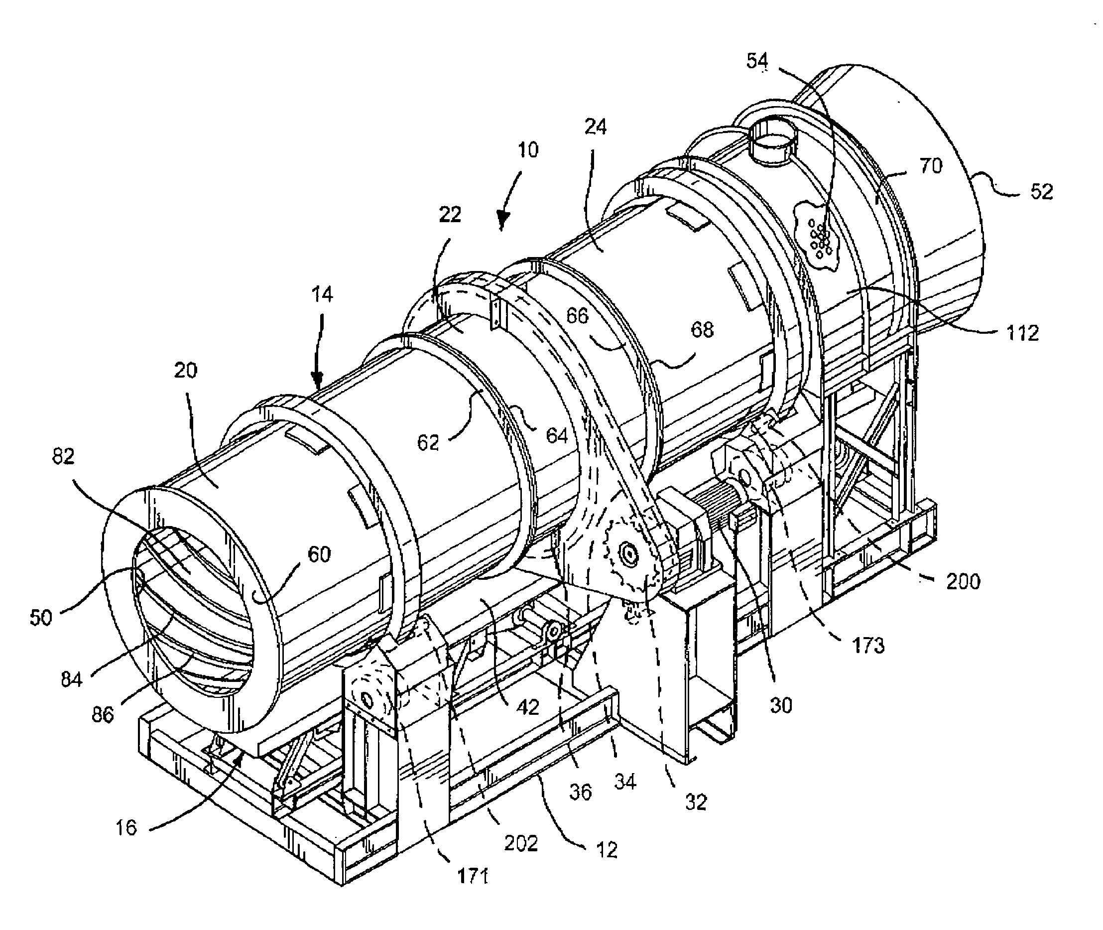
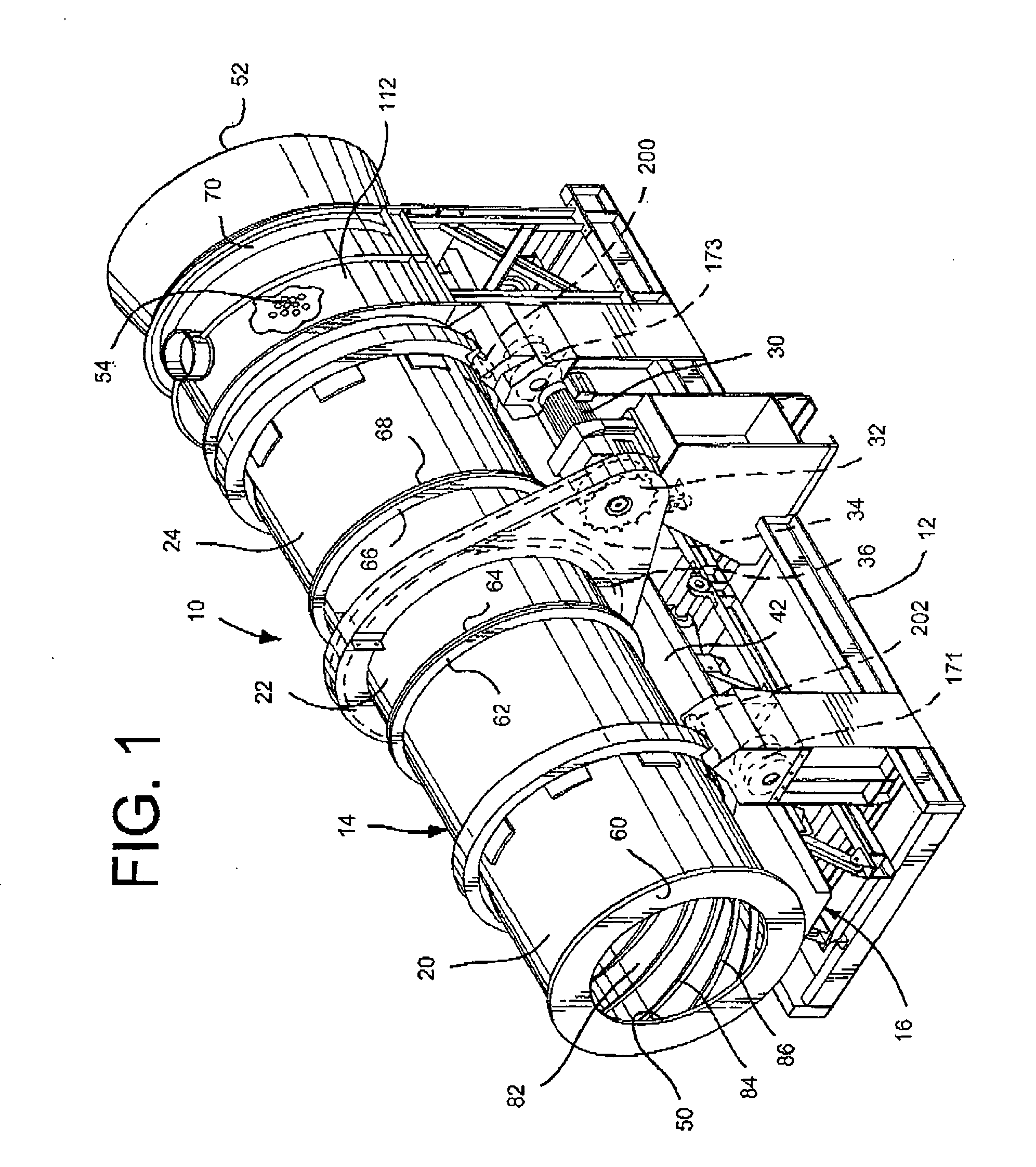
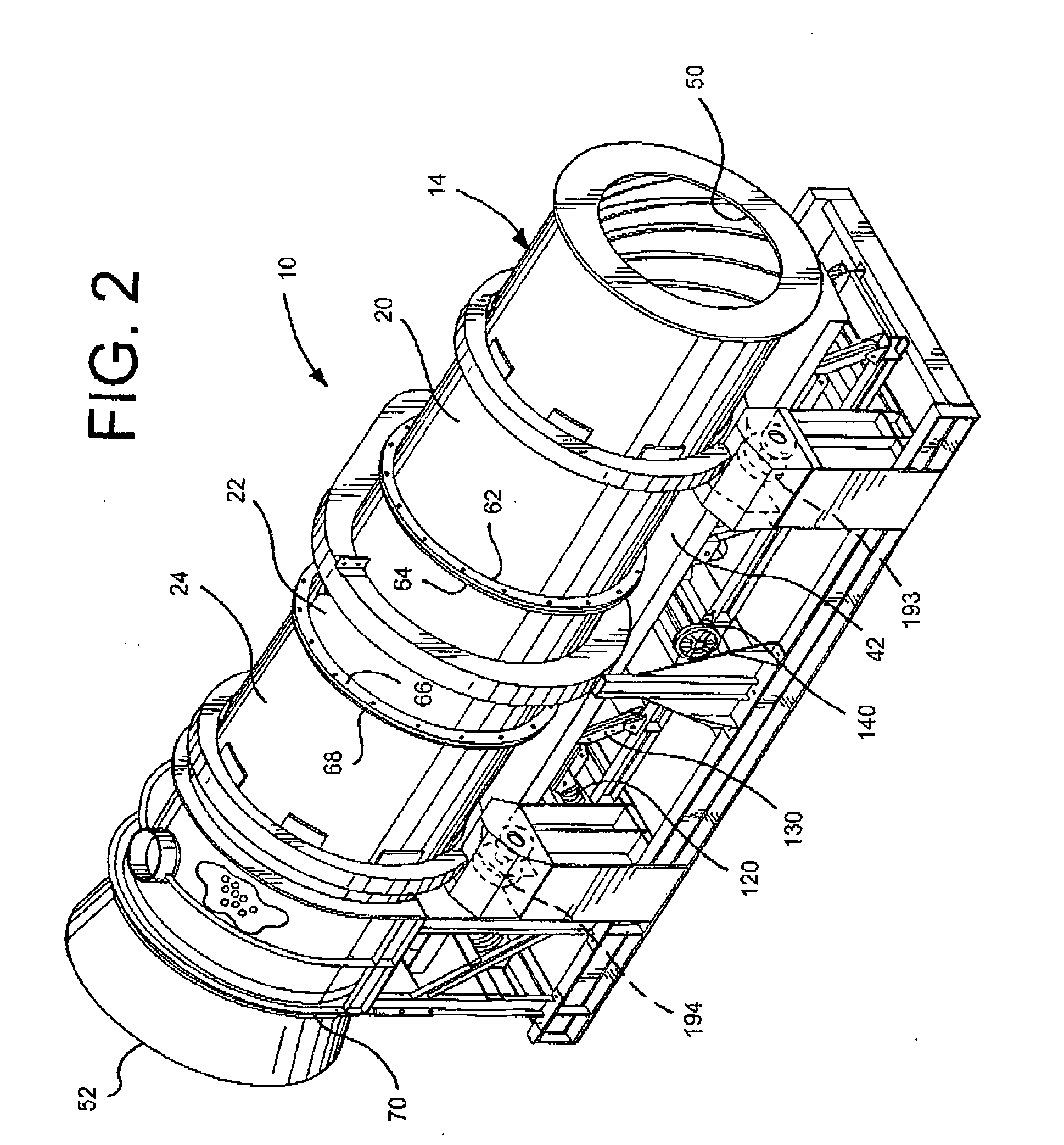
[0029]Referring now to FIGS. 1-5, there is shown a rotary drum and vibratory conveyor system 10 having a base fame 12 suppor...


PUM

PropertyMeasurementUnit
longitudinal lengthaaaaaaaaaa
sizesaaaaaaaaaa
movementaaaaaaaaaa

Abstract

A rotary drum and vibratory conveyor system including a single walled rotary drum positioned above a vibratory conveyor assembly. The rotary drum may be segmented with each segment having end flanges that are connected to an adjoining segment with bolts. A section or sections of the rotary drum have perforations covered by a dust hood that allow sand and media to fall from the drum through a funnel structure onto the conveyor assembly. The vibratory conveyor assembly includes upper and lower conveyors, where the upper conveyor collects the media falling from the drum and passes the sand to the lower conveyor. The media may be redirected back to the drum inlet to be reused.

Description

BACKGROUND OF THE INVENTION[0001]1. Field of the Invention[0002]The present invention relates to a rotary drum and conveyor system, and more particularly, to a single walled rotary drum with perforations and a vibratory conveyor system.[0003]2. Description of the Related Art[0004]Devices found in the related art use a rotary drum having inner and outer shells, the inner shell consisting of a removable liner and the outer shell functioning to retain sand and media.[0005]Such prior art having inner and outer shells are readily shown in U.S. Pat. Nos. 3,998,262, 4,674,691, 4,981,581, 5,016,827, 5,095,968, and 5,267,603 all of which are incorporated herein by reference. These patents disclose a double shelled machine that are very expensive to maintain, as their inner liner design is not easy to repair or replace, and if one section breaks in the double shelled devices, the entire liner has to be removed to repair the one section.BRIEF SUMMARY OF THE INVENTION[0006]Without limiting the ...

Claims


Application Information

Patent Timeline
Patent Type & Authority Applications(United States)
IPC IPC(8): B22D11/128B22D27/08
CPCB22D31/007B22C5/085
Inventor MUSSCHOOT, THOMAS PAULKEMPF, RICHARD
Owner GENERAL KINEMATICS CORP
Learn More