System and Method to Reduce Thermal Energy in Vehicle Interiors Subjected to Solar Radiation

a technology of solar radiation and thermal energy, applied in the direction of light to electrical conversion, vessel parts, vessel construction, etc., can solve the problems of increasing increasing interior temperature, and inability to escape thermal radiation created by the increase in interior air and surface temperature, etc., to achieve the effect of reducing thermal energy

Inactive Publication Date: 2009-11-19
GM GLOBAL TECH OPERATIONS LLC
View PDF21 Cites 30 Cited by
  • Summary
  • Abstract
  • Description
  • Claims
  • Application Information

AI Technical Summary

Benefits of technology

[0010]A method of reducing thermal energy in the interior of a parked vehicle is also provided. The method may include: A) Sensing whether the vehicle is occupied and whether the vehicle is running; B) monitoring the temperature of the vehicle interior while the vehicle is not running and is unoccupied; C) comparing the monitored temperature to a predetermined target temperature, which may be based upon occupant comfort; D) and, circulating ambient air through the vehicle interior if the monitored temperature is greater than the predetermined target temperature. Some embodiments of the method may include powering the air circulation with energy derived from sources other than the vehicle engine.

Problems solved by technology

Unoccupied vehicles parked in areas exposed to the sun often receive large amounts of solar radiation, which may cause the interior temperature of the vehicle to increase.
Increased interior air and surface temperatures may be uncomfortable to occupants upon returning to the vehicle.
The temperature increases because solar radiation is able to enter the car but the thermal radiation it creates is not able to escape.

Method used


Image

  • System and Method to Reduce Thermal Energy in Vehicle Interiors Subjected to Solar Radiation
  • System and Method to Reduce Thermal Energy in Vehicle Interiors Subjected to Solar Radiation
  • System and Method to Reduce Thermal Energy in Vehicle Interiors Subjected to Solar Radiation

Examples


Embodiment Construction

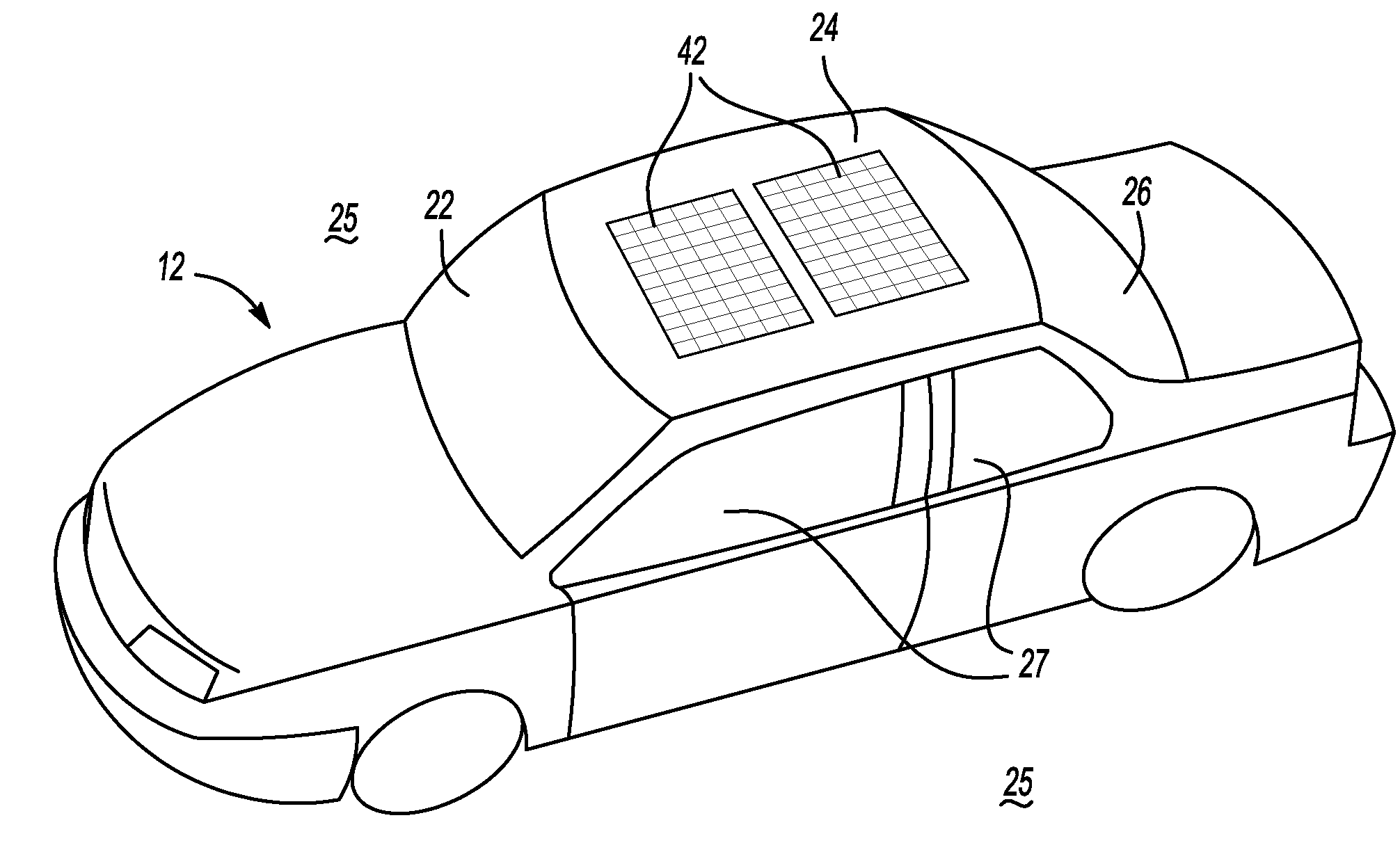
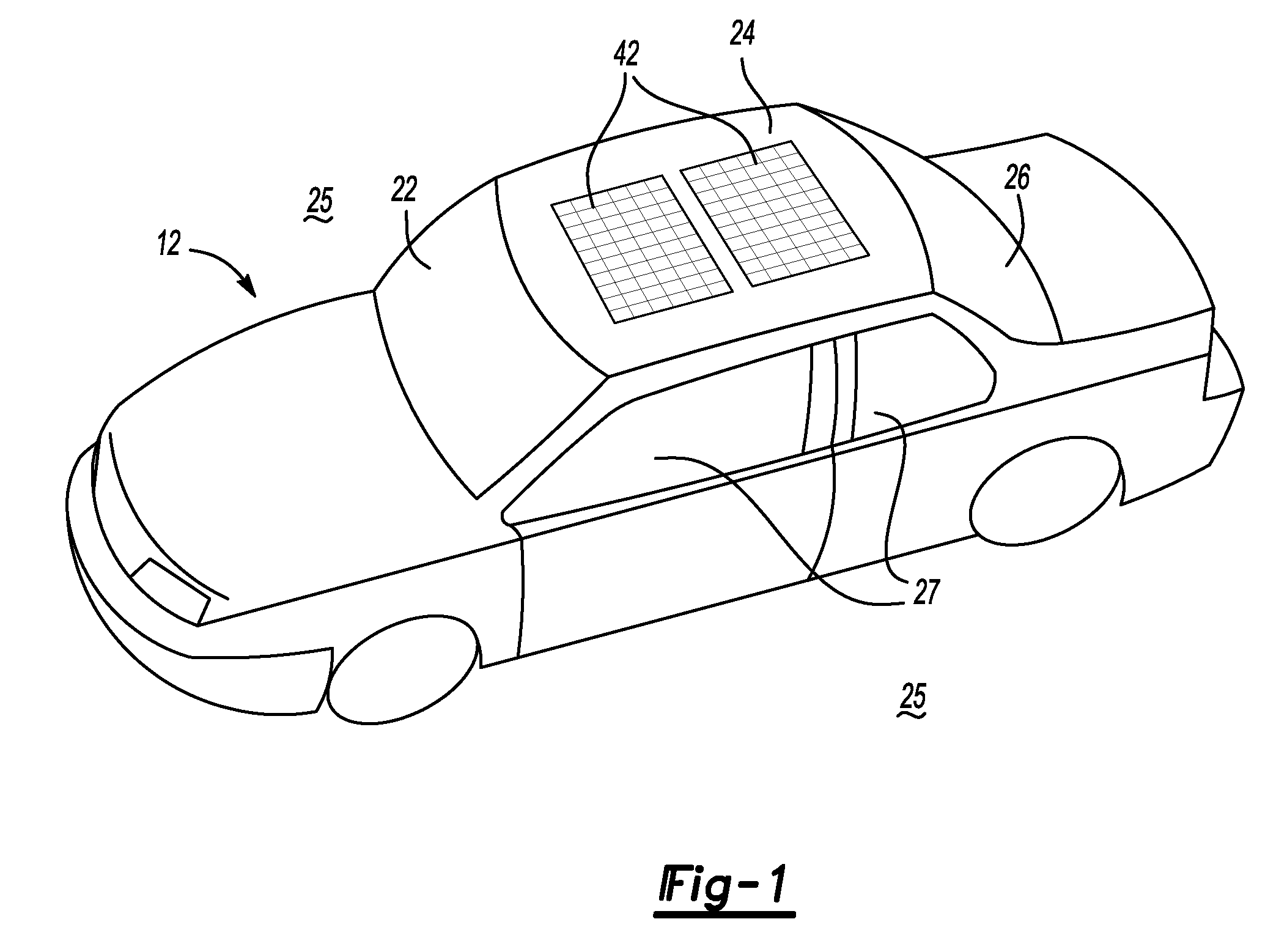
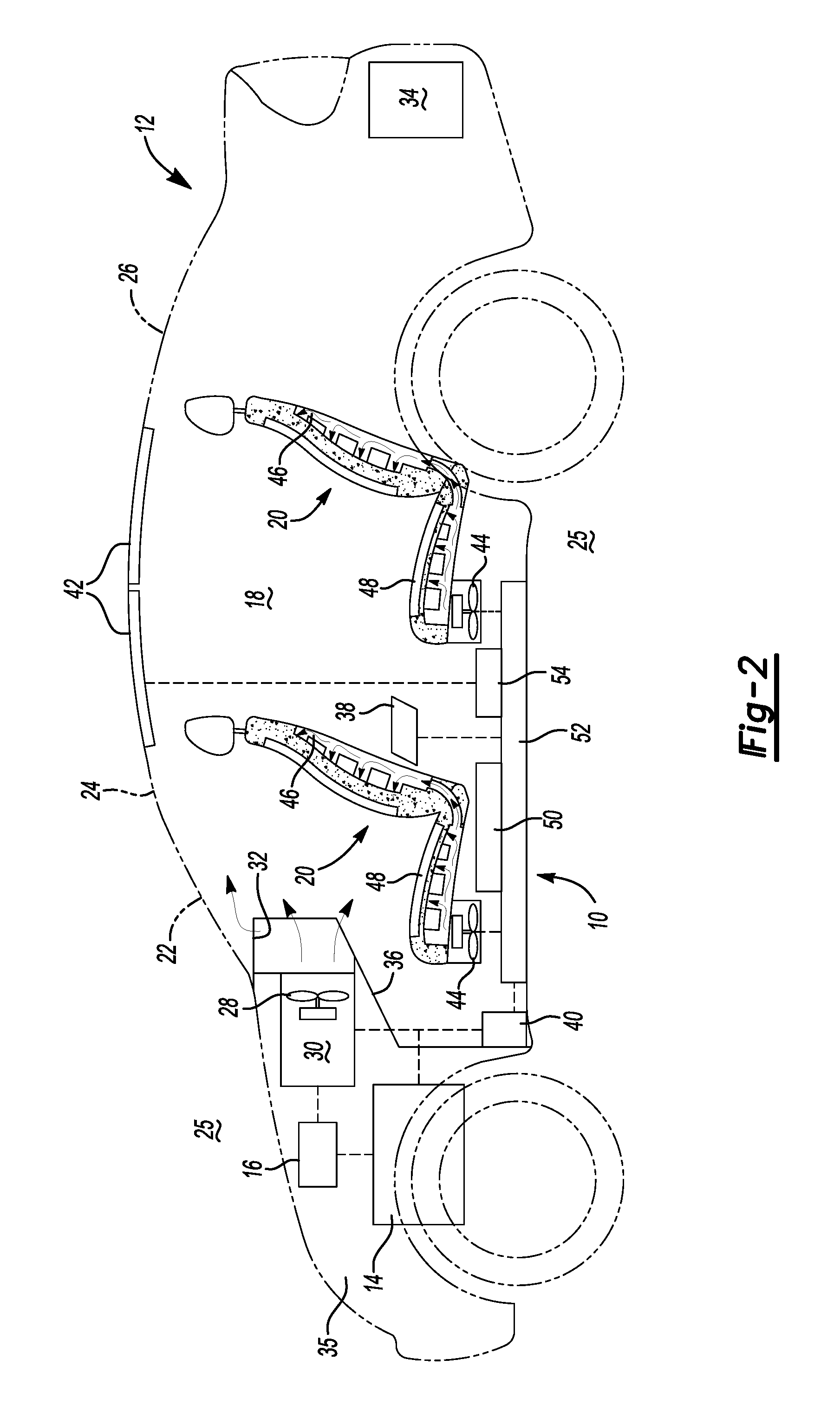
[0015]Referring to the drawings, wherein like reference numbers correspond to like or similar components throughout the several figures, there is schematically shown in FIG. 2 an embodiment of a thermal energy reduction system 10 placed in a vehicle 12. Those having ordinary skill in the art will recognize that the thermal energy reduction system 10 may be incorporated into various types of vehicles 12, such as, without limitation: cars, trucks, vans, sport-utility vehicles, et cetera.

[0016]Vehicle 12 has an engine 14, which may be an internal combustion engine or another engine, such as, without limitation: an electric propulsion, hybrid, or fuel cell propulsion system, known to those having ordinary skill in the art. While the vehicle 12 is being driven, the engine 14 provides propulsion and generates power which may be stored in a starter battery 16.

[0017]As will be recognized by those having ordinary skill in the art, the starter battery may provide multiple functions for vehicl...


PUM


Abstract

A system for reducing thermal energy in the interior of an unoccupied vehicle includes an energy source, a temperature sensor, and a control unit which triggers the system in response to satisfaction of conditions. The conditions include the temperature of the passenger compartment being greater than a target temperature and the vehicle engine not running. A fan configured to selectively bring ambient air into the passenger compartment is powerable by the energy source and circulates ambient air through the passenger compartment in response to the control unit. The energy source may include a solar panel or another source characterized by absence of energy derived from the vehicle engine, and excess energy may be distributed to an energy storage device. A seat ventilation fan may operate concurrently with the fan or an HVAC. A method of reducing thermal energy in the interior of a parked vehicle is also provided.

Description

TECHNICAL FIELD[0001]This disclosure relates to a system and method for reduction of stored thermal energy in vehicle interiors.BACKGROUND OF THE INVENTION[0002]Unoccupied vehicles parked in areas exposed to the sun often receive large amounts of solar radiation, which may cause the interior temperature of the vehicle to increase. This may be called a solar soak. Incoming solar radiation from the sun warms thermal masses inside of the vehicle, such as the seats, dashboard, door panels, and console. Air warmed by the heat from hot interior surfaces is retained by the windows and roof, and the interior, therefore, may reach temperatures higher than the temperature of the ambient air outside of the vehicle.[0003]Increased interior air and surface temperatures may be uncomfortable to occupants upon returning to the vehicle. Thus, reducing surface and cushion temperatures will increase comfort on entry.[0004]The temperature increases because solar radiation is able to enter the car but t...

Claims


Application Information

Patent Timeline
Patent Type & Authority Applications(United States)
IPC IPC(8): B60H1/24
CPCB60H1/00428B60H1/00778B60H1/00807B60H1/24Y02T10/7083B60L8/003B60N2/5635B60N2/5657B60L1/02Y02T10/7072Y02T10/88
Inventor MAJOR, GREGORY A.FREY, JOHN I.
Owner GM GLOBAL TECH OPERATIONS LLC
Why Eureka
Try Eureka