Systems and methods for stone removal

Inactive Publication Date: 2009-11-19
PERCUTANEOUS SYST
View PDF8 Cites 26 Cited by
  • Summary
  • Abstract
  • Description
  • Claims
  • Application Information

AI Technical Summary

Benefits of technology

[0013]While in some instances the sweeping structure may comprise balloons, cages, or other structures, it will be preferred to use a compacted length of material which provides a number of advantages. The length of material will generally be relatively flexible or soft and will be atraumatic when it is compacted within the ureter. The compacted length of material will also conform to non-circular ureter geometries as well as to the irregular shape of the kidney stone prior to disruption. Additionally, the length of material can typically be drawn to a very thin profile, thus facilitating introduction of the length of material past the kidney stone prior to compaction and enlargement. The ability to stretch and draw down the width of the material is also advantageous if it is desired to withdraw the occluding structure from the ureter and / or to release the stone or stone fragments which may have been captured in the compacted material. Such release is very difficult with a wire basket or similar structure.
[0016]In a second aspect of the present invention, a method for urinary stone removal comprises deploying a sweeping structure on a kidney side of a urinary stone in a ureter. The sweeping structure is then drawn in an antegrade direction to pull the urinary stone from the end of the ureter and into the bladder. If the urinary stone resists being pulled by the sweeping structure, the treating physician may then introduce a dilating structure, typically coaxially over the shaft of the sweeping structure, so that it lies on the bladder side of the kidney stone. The dilating structure is then expanded to open the ureter and dislodge the stone. The sweeping structure may then be drawn to pull the dislodged urinary stone with or without the dilating structure into the bladder. Should dislodgement of the stone using the dilating structure prove insufficient, the user may then introduce a lithotripsy device into the ureter while the sweeping catheter remains in place. Energy from the lithotripsy device may then be directed into the urinary stone to fragment the stone. The sweeping structure may then be drawn to pull the fragmented stone into the bladder. Typically, the dilating structure will be left in place during use of the lithotripsy device. The open scaffold or other structure of the dilating structure allows the device to be introduced through the structure to contact the stone. Alternatively, energy from the device could be directed at the stone after removal of the open dilating structure, the prior dilation providing improved access. The use of the open dilating structure in particular, is further advantageous as it permits viewing of the stone using an endoscope or other means during removal or fragmentation.

Problems solved by technology

Such release is very difficult with a wire basket or similar structure.

Method used


Image

  • Systems and methods for stone removal
  • Systems and methods for stone removal
  • Systems and methods for stone removal

Examples


Embodiment Construction

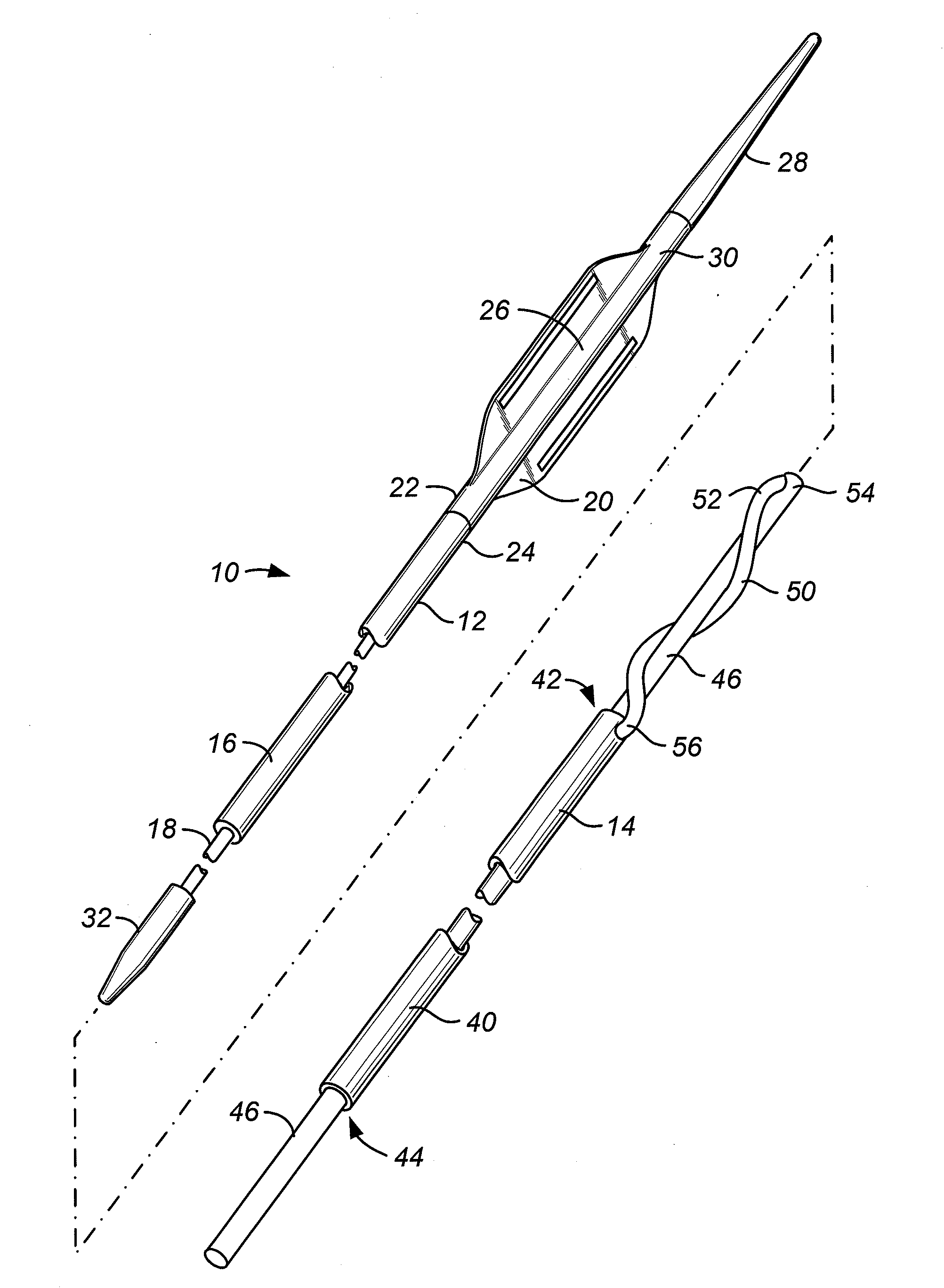
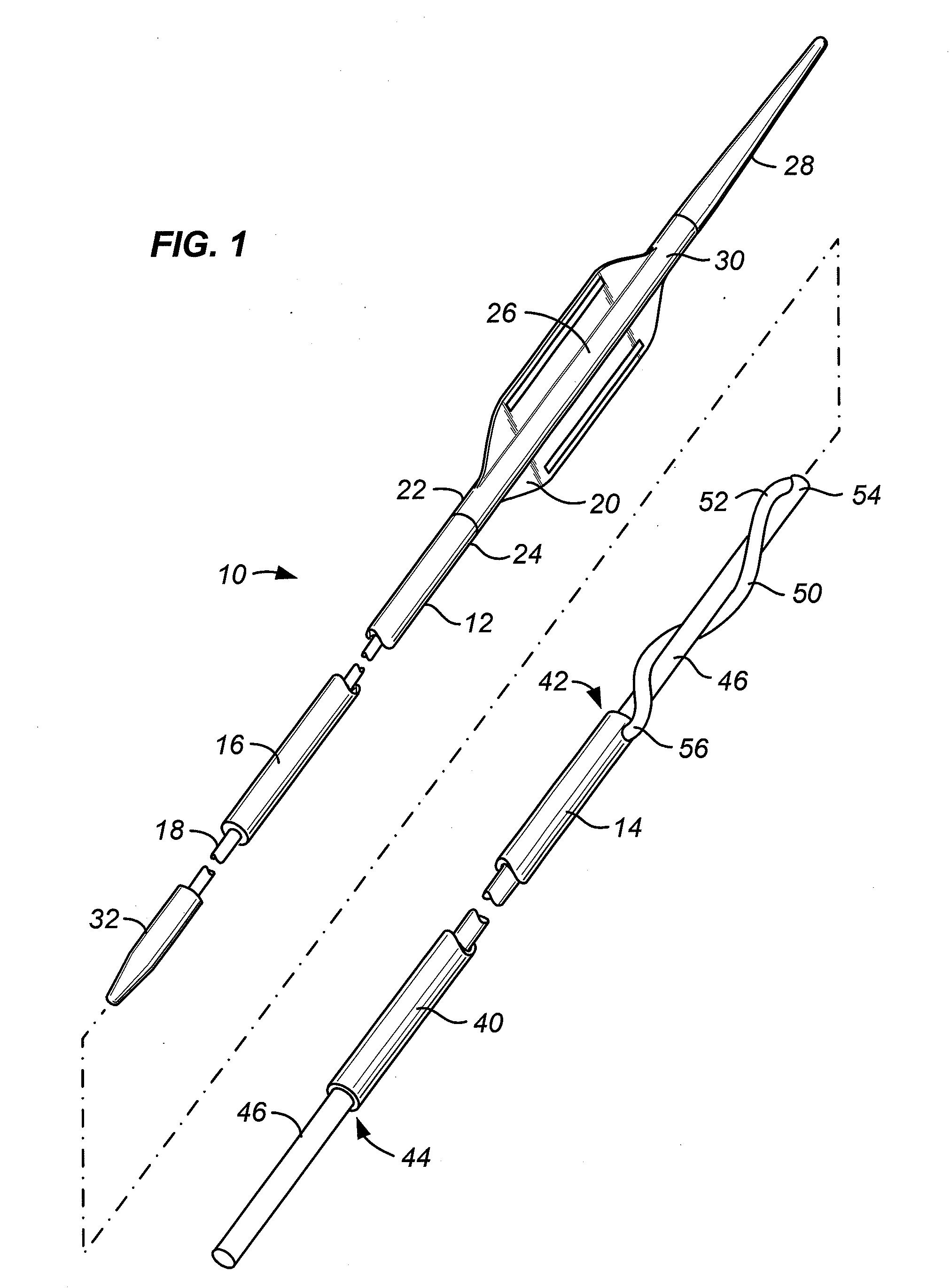
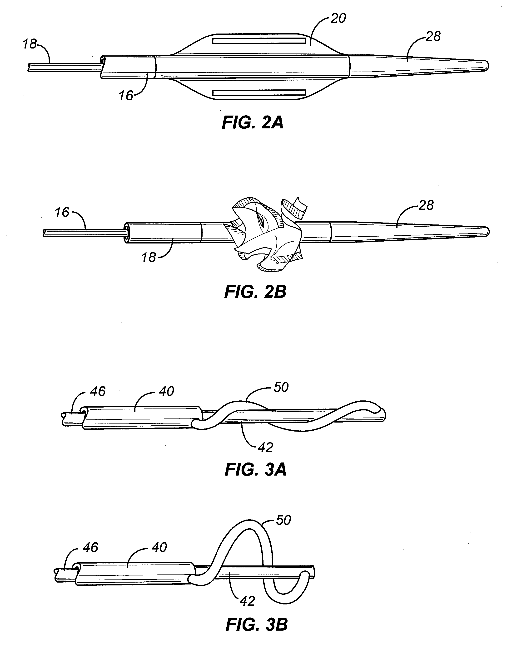
[0027]Referring now to FIG. 1, a stone removal system 10 constructed in accordance with the principles of the present invention comprises a sweeping structure 12 and a dilating structure 14. The sweeping structure 12 typically comprises a shaft 16 which slidably receives a rod 18 in a central passage thereof. A flat film 20 has a proximal end 22 attached to a distal end 24 of the shaft. The rod 18 extends through or over the length of the flat film 20, typically being positioned within a lumen 26 formed in the film. Usually, the rod 18 terminates in an atraumatic tip 28, where a distal end 30 of the film is attached to the rod just proximally of the atraumatic tip 28.

[0028]As illustrated in FIGS. 2A and 2B, the flat film 20 may be axially foreshortened and radially expanded by pulling or tensioning the rod 18 in a proximal direction relative to the shaft 16. Flat film 20 in its foreshortened, radially expanded configuration is illustrated in FIG. 2B. The film will usually have a wid...


PUM


Abstract

A stone removal system comprises a sweeping structure and a dilating structure. The sweeping structure is deployed on a kidney side of a urinary stone in the ureter. Should the sweeping structure be unable to remove the kidney stone, the dilating structure is placed on the bladder side of the kidney stone and used to dilate the lumen of the ureter. The dilated lumen allows the sweeping structure to more easily remove the kidney stone. Should the kidney stone still resist removal, a lithotripsy device may be introduced through the ureter and energy directed through openings in the dilation structure to fragment the stone.

Description

CROSS-REFERENCES TO RELATED APPLICATIONS[0001]The present application claims the benefit of U.S. provisional patent application No. 61 / 053,742 (Attorney Docket No. 021807-004100US) filed on May 16, 2008, and the benefit of U.S. Provisional Patent Application No. 61 / 118,802 (Attorney Docket No. 021807-004200US), filed on Dec. 1, 2008, the full disclosures of which are incorporated herein by reference. The present application is related to, but does not claim the benefit of, the following commonly-owned U.S. patent application Ser. No. 12 / 041,241 (Attorney Docket No. 021807-004010US) filed on Mar. 3, 2008; Ser. No. 11 / 777,522 (Attorney Docket No. 02807-004000US), filed on Jul. 13, 2007; Ser. No. 10 / 886,886 (Attorney Docket No. 021807-000800US), filed on Jul. 7, 2004; and Ser. No. 11 / 777,515 (Attorney Docket No. 021807-000830US), filed on Jul. 13, 2007, the full disclosures of which are incorporated herein by reference.BACKGROUND OF THE INVENTION[0002]1. Field of the Invention.[0003]Th...

Claims


Application Information

Patent Timeline
IPC IPC(8): A61B17/22
CPCA61B17/22012A61B17/22031A61B17/221A61B18/24A61B2017/00336A61M2025/109A61B2017/2212A61B2017/2217A61M25/0068A61M29/02A61B2017/00849
Inventor DESAI, RUPESHYEE, STEVEN
Owner PERCUTANEOUS SYST
Why Eureka
Try Eureka