Photovoltaic power generation and solar heat collector

a technology of solar heat collectors and photovoltaic power, applied in the direction of electrochemical generators, hybrid energy generation, lighting and heating apparatus, etc., can solve the problem of limited area of roofs or similar areas that are well exposed to sunlight, and achieve the effect of reducing generation efficiency, effective sunlight utilization, and removing heat and electric power

Inactive Publication Date: 2009-11-26
ELECTRIC POWER DEVELOPMENT COMPANY
View PDF2 Cites 42 Cited by
  • Summary
  • Abstract
  • Description
  • Claims
  • Application Information

AI Technical Summary

Benefits of technology

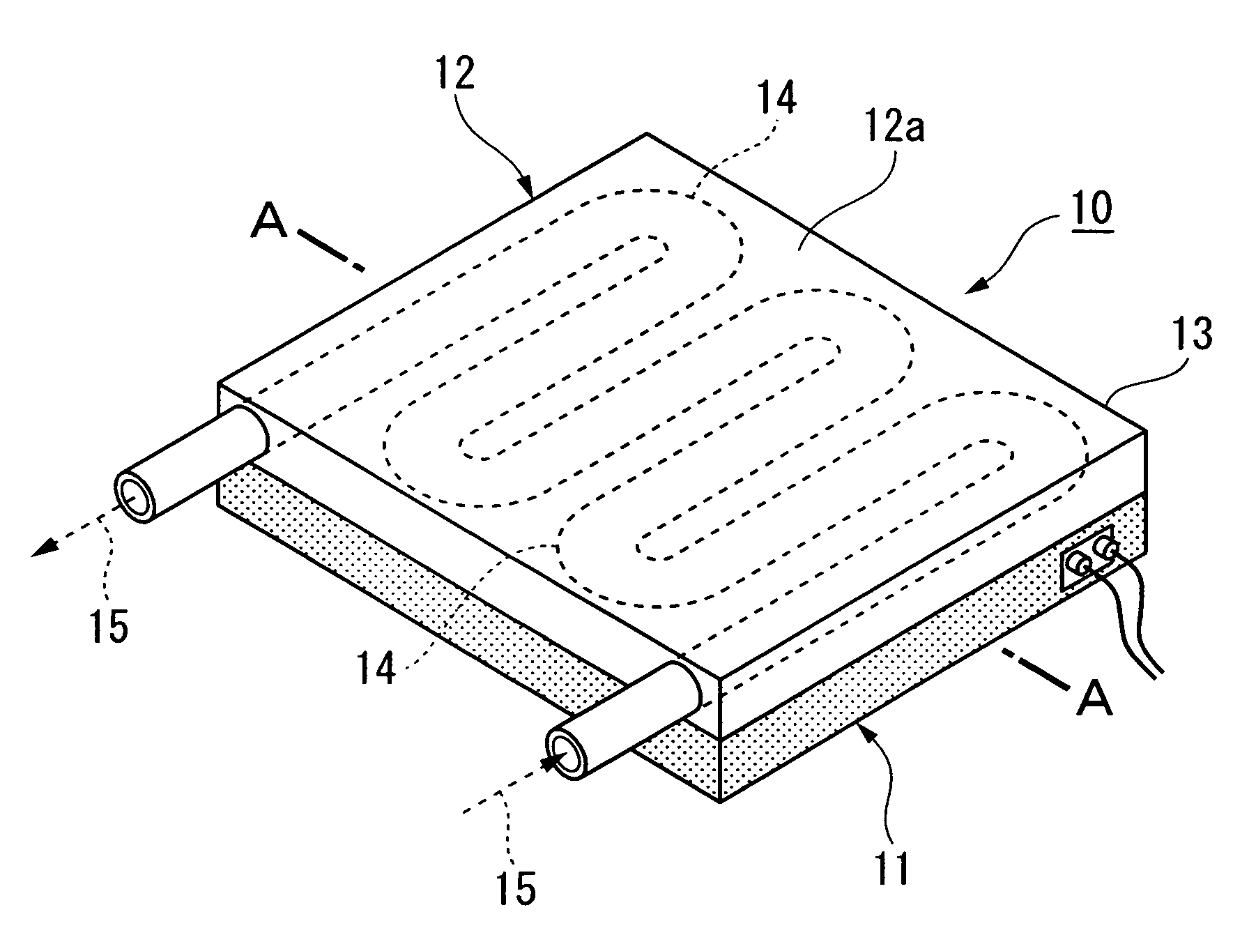
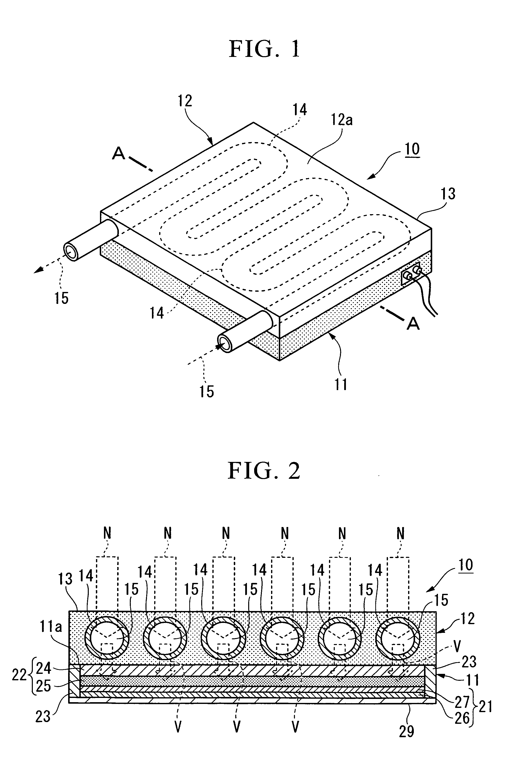
[0013]According to the present invention, the heat medium flowing through the heat collection panel is heated by rays in the infrared region (heat rays) included in sunlight, and electric power is generated by the photoelectric conversion in the dye-sensitized photovoltaic cell mainly by means of rays in the ultraviolet region. As a result, it is possible to effectively utilize sunlight over a wide range of wavelengths, and to remove heat and electric power.
[0014]Furthermore, with the formation of the heat collection panel on top or bottom of the dye-sensitized photovoltaic cell, the heat medium flowing through the heat collection panel is allowed to absorb the heat of the dye-sensitized photovoltaic cell, to thereby make it possible to cool the dye-sensitized photovoltaic cell. The dye-sensitized photovoltaic cell suffers from deterioration and evaporation of the electrolytic solution, a decrease in generation efficiency, and the like at elevated temperatures. However, with the formation of the heat collection panel in contact with the dye-sensitized photovoltaic cell, it is possible to prevent such an increase in temperature of the electrolytic solution, to thereby maintain the generation efficiency favorable while preventing deterioration of the dye-sensitized photovoltaic cell.
[0015]Furthermore, with the formation of the heat collection panel on top or bottom of the dye-sensitized photovoltaic cell, the installation area occupies only half or less of the case where the dye-sensitized photovoltaic cell and the heat collection panel are separately installed side by side. This allows efficient utilization of a roof of a building or the like which is limited in area, to thereby efficiently obtain heat and electric power from sunlight.

Problems solved by technology

However, a roof or the like that is well exposed to sunlight is limited in area.

Method used


Image

  • Photovoltaic power generation and solar heat collector
  • Photovoltaic power generation and solar heat collector
  • Photovoltaic power generation and solar heat collector

Examples


examples

[0088]Hereunder, a description of more specific exemplary constructions of the photovoltaic power generation and solar heat collector (hybrid panel) and verification results of the advantages according to the present invention are provided.

(Verification 1)

[0089]In the dye-sensitized photovoltaic cell constituting the hybrid panel, 10-cm-square glass plates with a thickness of 3 mm were used as support substrates, the glass plates having been cut out from a soda-lime glass plate (manufactured by Nippon Sheet Glass Co., Ltd.) on which was formed a transparent conducting film. In one of the glass substrates, a titanium oxide paste (SOLARONIX, trade name: Nanoxide HT) was applied with a thickness of 20 μm by the screen printing method on the surface where the transparent conducting film was formed. The applied film was fired at 450° C. for one hour. Furthermore, on this, a titanium oxide paste (SOLARONIX, trade name: Nanoxide D) was applied with a thickness of 20 μm. The applied film wa...


PUM


Abstract

Provided is a photovoltaic power generation and solar heat collector which can be installed in a small area and can simultaneously maintain a high collection efficiency and a high photoelectric conversion efficiency. The photovoltaic power generation and solar heat collector (10) includes a dye-sensitized photovoltaic cell (11); and a heat collection panel (12) provided on top of the dye-sensitized photovoltaic cell (11). Sunlight is incident on a top surface of the heat collection panel (12).

Description

TECHNICAL FIELD[0001]The present invention relates to a photovoltaic power generation and solar heat collector that collects heat from sunlight and performs photoelectric conversion from sunlight.[0002]Priority is claimed on Japanese Patent Application No. 2006-343025 filed on Dec. 20, 2006, the contents of which are incorporated herein by reference.BACKGROUND ART OF THE INVENTION[0003]These days, it has been widespread practice to install a photovoltaic cell or a heat collection panel (solar water heater and the like) on a roof or the like of a building for effective use of sunlight, to thereby reduce gas and electricity consumption. A heat collection panel, which utilizes heat from sunlight, is completely different in construction from a photovoltaic cell, which utilizes sunlight as electric power by photoelectric conversion. Therefore, for such utilization of sunlight, it has been conventionally required to selectively install either one or to install both of them side by side.[0...

Claims


Application Information

Patent Timeline
Patent Type & Authority Applications(United States)
IPC IPC(8): H01L31/00H01L31/058
CPCF24J2/268F24J2002/0092H01G9/20H01M14/005H02S40/44Y02B10/20Y02E10/44Y02E10/542Y02E10/60Y02B10/12F24S10/755F24S2020/17Y02B10/10H01L31/04H01M14/00
Inventor HIWATASHI, KENICHIMASUYAMA, NAOTO
Owner ELECTRIC POWER DEVELOPMENT COMPANY
Why Eureka
Try Eureka