Payment terminal stylus with touch screen contact detection

a payment terminal and touch screen technology, applied in the field of payment terminals with touch screens and stylus, can solve the problems of inability to transmit sense signals, difficulty in obtaining personal information based on finger or pen location, and inability to operate the stylus,

Active Publication Date: 2009-11-26
HYPERCOM CORP
View PDF1 Cites 115 Cited by
  • Summary
  • Abstract
  • Description
  • Claims
  • Application Information

AI Technical Summary

Benefits of technology

[0008]In accordance with various aspects of the present invention, a method and device for a more operable stylus and touch screen is disclosed. In an exemplary embodiment, a stylus operates with a capaciti

Problems solved by technology

Also a capacitive screen is more secure because it is difficult for an unauthorized person to obtain personal information based on finger or pen location as the signals from the touch screen undergo a high speed multiplexed scanning.
However, one of the disadvantages is that a capacitive screen may activate when a stylus or a finger is approaching, or is near to the surface of the touch panel, rather than only when in contact with it.
Therefore, if the pen is not pressed down hard enough, or if there is a problem with creating sufficient electrical contact, the transmittin

Method used


Image

  • Payment terminal stylus with touch screen contact detection
  • Payment terminal stylus with touch screen contact detection
  • Payment terminal stylus with touch screen contact detection

Examples


Embodiment Construction

[0016]The present invention may be described herein in terms of various functional components and various processing steps. It should be appreciated that such functional components may be realized by any number of hardware or structural components configured to perform the specified functions. For example, the present invention may employ various integrated components, such as transistors, amplifiers, buffers, and logic devices comprised of various electrical devices, e.g., resistors, capacitors, diodes and the like, whose values may be suitably configured for various intended purposes. Further, it should be noted that while various components may be suitably coupled or connected to other components within exemplary circuits, such connections and couplings can be realized by direct connection between components, or by connection through other components and devices located thereinbetween.

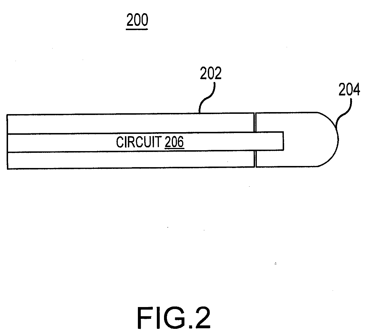
[0017]In accordance with an exemplary embodiment and with reference to FIG. 2, a stylus 200 comp...


PUM


Abstract

In an exemplary embodiment, a stylus operates with a capacitive touch screen only when the stylus tip is in contact with the touch screen. The stylus is used as a sensor to determine the location where a user is touching the surface of a capacitive touch screen, but is not active until the stylus tip is pressed against the touch screen. In an exemplary embodiment, pressing the stylus tip against the touch screen activates the stylus by creating a physical separation in the circuit and disconnecting the stylus tip from ground. When the stylus tip is no longer grounded, it becomes active and is able to operate with a capacitive touch screen. In an exemplary embodiment, signal attenuation may be performed by diverting the sense signal to ground via a capacitor or other electronic component.

Description

CROSS-REFERENCE TO RELATED APPLICATIONS[0001]This application claims priority to and benefit of U.S. Provisional Application No. 61 / 055,077, filed May 21, 2008, and entitled “PAYMENT TERMINAL STYLUS WITH TOUCH SCREEN CONTACT DETECTION”, and hereby incorporated by reference.FIELD OF INVENTION[0002]The present invention relates, generally, to point of sale (“POS”) terminals incorporating touch screens, and more particularly to payment transaction POS terminals with touch screens and a stylus.BACKGROUND OF THE INVENTION[0003]Point of sale (“POS”) terminals enable convenient electronic payment for many products and services. For example, consumers holding cards associated with a charge, credit, debit, or loyalty accounts may pay for a purchase simply by using the card with a POS terminal located at stores, restaurants, and other locations where the products and services are being purchased. During the transaction, as part of the process the customer (card holder) may make payment select...

Claims


Application Information

Patent Timeline
IPC IPC(8): G06F3/033
CPCG06F3/03545
Inventor HENRY, CHRIS
Owner HYPERCOM CORP
Why Eureka
Try Eureka