
Display device

a display device and display technology, applied in the field of display devices, can solve the problems of inability to improve the contrast of still images and the quality of moving images, and achieve the effects of improving image quality, improving contrast ratio, and increasing peak luminan

Active Publication Date: 2009-11-26
SEMICON ENERGY LAB CO LTD
View PDF13 Cites 84 Cited by
  • Summary
  • Abstract
  • Description
  • Claims
  • Application Information

AI Technical Summary

Benefits of technology

[0010]In view of the foregoing problems, an object of an embodiment of the present invention is to improve the image quality when still images and moving images are displayed. Another object of an embodiment of the present invention is to improve the contrast ratio when still images and moving images are displayed. Another object of an embodiment of the present invention is to increase the viewing angle when still images and moving images are displayed. Still another object of an embodiment of the present invention is to increase the response speed when still images and moving images are displayed. Another object of an embodiment of the present invention is to reduce power consumption when still images and moving images are displayed. Another object of an embodiment of the present invention is to reduce manufacturing costs.
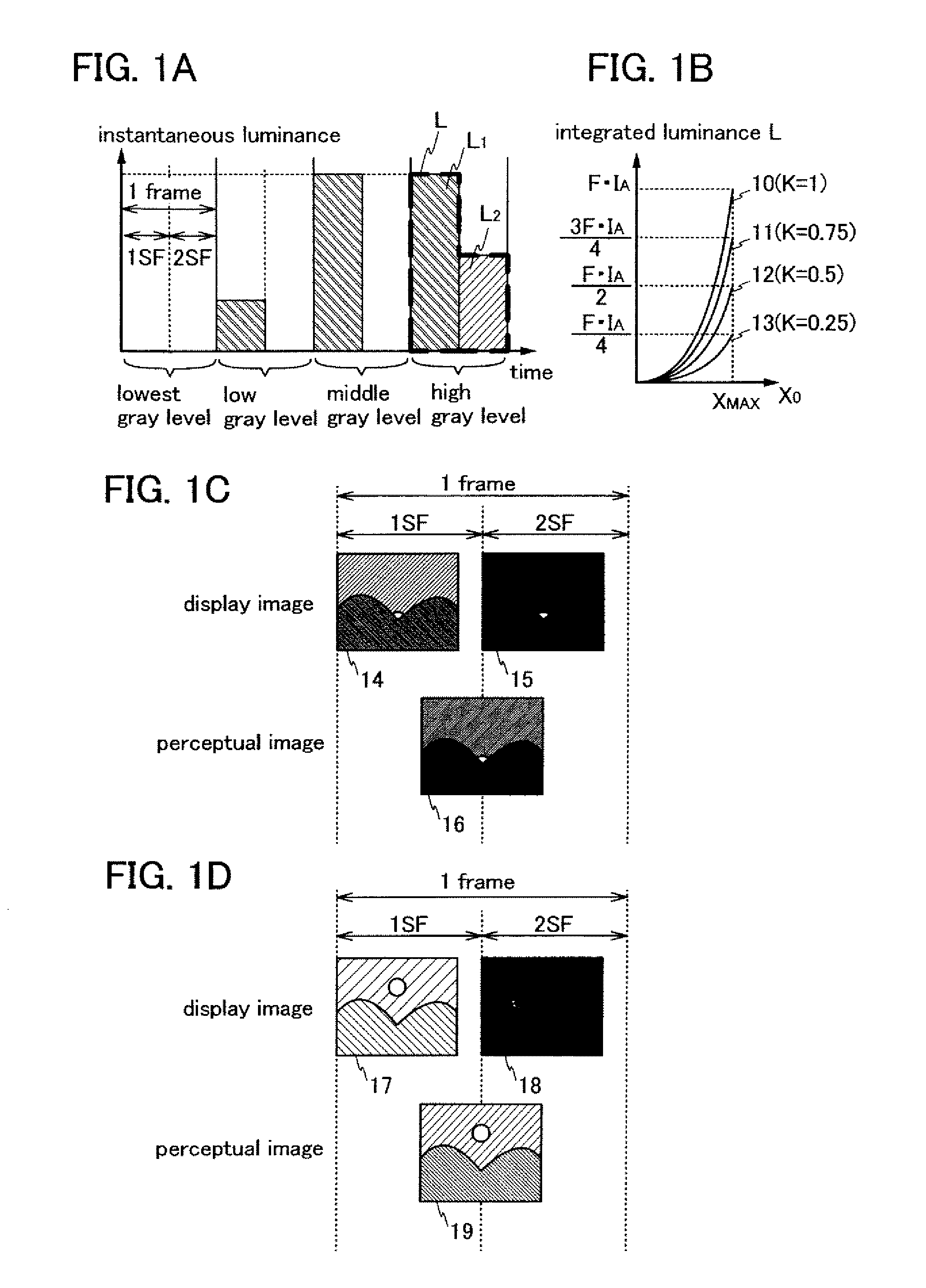
[0080]According to one embodiment of the present invention the peak luminance can be increased depending on gray level data distribution, which leads to improvement in image quality. According to one embodiment of the present invention, faint light emission at the time of black display is not increased even when the peak luminance is increased, whereby the contrast ratio can be increased. According to one embodiment of the present invention, an optical state of liquid crystal molecules is averaged by alternately displaying a generally bright image and a generally dark image, whereby the viewing angle can be increased. According to one embodiment of the present invention, the response speed of a liquid crystal element can be increased. According to one embodiment of the present invention, the efficiency of a backlight is increased, which results in reduction in power consumption. According to one embodiment of the present invention, a desired gray level is expressed by alternately displaying a generally bright image and a generally dark image, whereby the quality of moving images can be improved. According to one embodiment of the present invention, manufacturing costs can be reduced.

Problems solved by technology

In the technique disclosed in Patent Document 1, the time for displaying a black image is short when an image is generally dark; thus, an afterimage due to hold driving occurs, which leads to a problem with the quality of moving images.
That is, since the luminance of the backlight is controlled only in accordance with an image as appropriate, the contrast of still images cannot be improved.
Further, Patent Document 2 does not disclose any solution for improving quality of moving images, which is one of major problems that liquid crystal display devices have.

Method used


Image

  • Display device
  • Display device
  • Display device

Examples


embodiment 1

[0106]As Embodiment 1, a structure example and a driving method of a display device will be described.

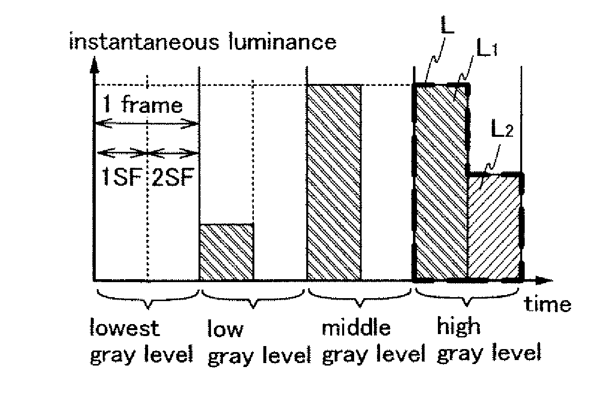
[0107]First, terms used in this embodiment and other embodiments are described. The human eye cannot perceive change of luminance which changes faster than a certain frequency (the critical frequency). Specifically, the human eye cannot perceive change of luminance which changes at a frequency of approximately 50 Hz or more, that is, in 20 milliseconds or less, and perceives such change of luminance as certain brightness. At this time, the brightness perceived by the human eye depends on the level obtained by integrating instantaneous luminance with the time.

[0108]In this embodiment and other embodiments, when it is necessary to explicitly describe luminance that is instantaneously obtained, such luminance is referred to as instantaneous luminance. Moreover, when it is necessary to explicitly describe the level obtained by integrating instantaneous luminance with the time, such leve...

embodiment 2

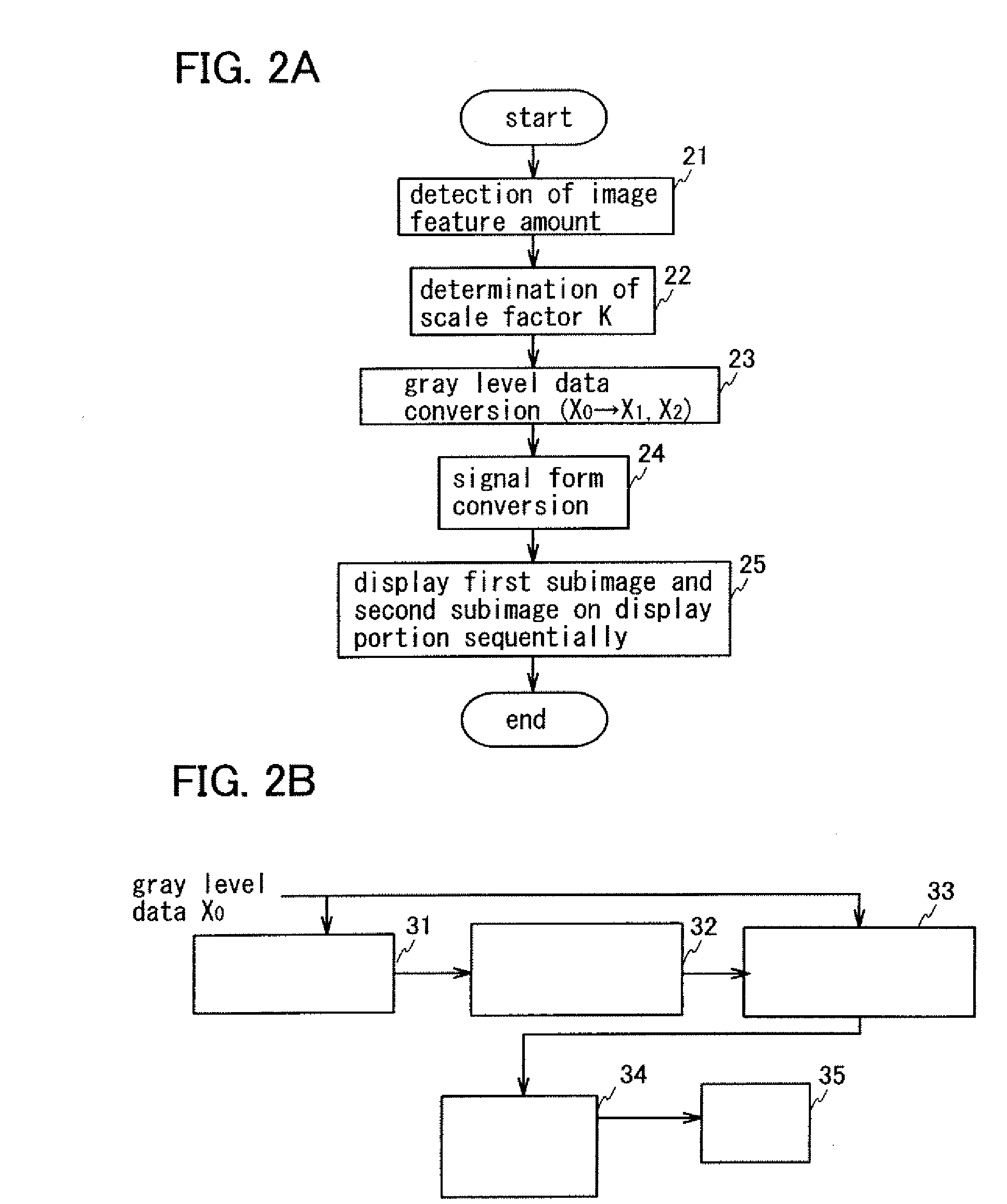
[0147]As Embodiment 2, another structure example and a driving method of a display device will be described. In this embodiment, an example of a specific method for determining the scale factor K, and specific structure examples and operations of the image feature amount detection portion 31 and the scale factor determination portion 32 in FIG. 2B will be described.

[0148]A display device in this embodiment performs operations detailed more than or different from the operation 21 (detection of the image feature amount) and the operation 22 (determination of the scale factor K) among the operations (FIG. 2A) of the display device in Embodiment 1. The other operations and structures are similar to those in the display device in Embodiment 1; therefore, the detail description is not repeated.

[0149]First, the operation flow of the display device in this embodiment and means to perform such operations will be described. FIGS. 5A to 5C are flowcharts each illustrating a detailed example of...

embodiment 3

[0196]As Embodiment 3, another structure example and a driving method of a display device will be described. In this embodiment, an example of a specific method of determining gray level data conversion, and a specific structure example and a driving method of the gray level data conversion portion 33 in FIG. 21 will be described.

[0197]A display device in this embodiment performs an operation detailed more than or different from the operation 23 (gray level data conversion) among the operations (FIG. 2A) of the display device in Embodiment 1. The other operations and structures are similar to those in the display device in Embodiment 1; therefore, the detail description is not repeated.

[0198]First, the operation flow of the display device in this embodiment and means to perform such operations will be described. FIG. 8A is a flowchart illustrating a detailed example of the operation 23 in FIG. 2A. FIG. 8B illustrates an example of a structure of a device for realizing the operations...


PUM


Abstract

A display device in which the image quality is improved by control of the peak luminance. A plurality of instantaneous luminances are expressed by performing signal writing to each pixel plural times within one frame period. The gray level is expressed by controlling time integration levels of the plurality of instantaneous luminances. Moreover, the time integration level is increased as the level of gray level data of the pixel is higher, and the time integration level is increased as the average value of gray level data of an image to be displayed is smaller.

Description

BACKGROUND OF THE INVENTION[0001]1. Field of the Invention[0002]The present invention relates to a display device and a semiconductor device, and more particularly to a hold-type display device such as a liquid crystal display device. The present invention especially relates to a method for driving a liquid crystal display device in which peak luminance is controlled. Further, the present invention relates to an electronic device including such a display device for a display portion.[0003]2. Description of the Related Art[0004]A liquid crystal display device has advantages such as small thickness, lightness in weight, and low power consumption as compared to a display device using a cathode-ray tube (CRT). Further, since a liquid crystal display device can be applied to a wide range of display devices from a small display device including a display portion with a few inches diagonal to a large display device including one with a diagonal of more than 100 inches, the liquid crystal d...

Claims


Application Information

Patent Timeline
IPC IPC(8): G09G5/10
CPCG09G3/2025G09G2360/16G09G3/3406G09G3/3614G09G3/3648G09G2300/0443G09G2300/0491G09G2310/0232G09G2320/0252G09G2320/0261G09G2320/0276G09G2320/0646G09G2320/10G09G2330/021G09G3/2081
Inventor YOSHIDA, YASUNORI
Owner SEMICON ENERGY LAB CO LTD
Learn More