Bone conduction speaker

Inactive Publication Date: 2009-11-26
TEMCO JAPAN
View PDF0 Cites 76 Cited by
  • Summary
  • Abstract
  • Description
  • Claims
  • Application Information

AI Technical Summary

Benefits of technology

[0014]The bone conductive speaker in accordance with the present invention comprises a bone conductive speaker body and holding means which is attached to the bone conductive speaker body to hold the bone conductive speaker body so that the bone conductive speaker body is brought into contact with the tragus or a portion in the vicinity thereof, and has a simple configuration such that the holding means is of a ring shape having a size accommodated in the concha cavity, and both outside face parts thereof come into con

Problems solved by technology

In this method, it was irksome to continuously put the headband on the head, and the wearing state was conspicuous.
As a result, there arises a problem in that the bone condu

Method used


Image

  • Bone conduction speaker
  • Bone conduction speaker
  • Bone conduction speaker

Examples


first embodiment

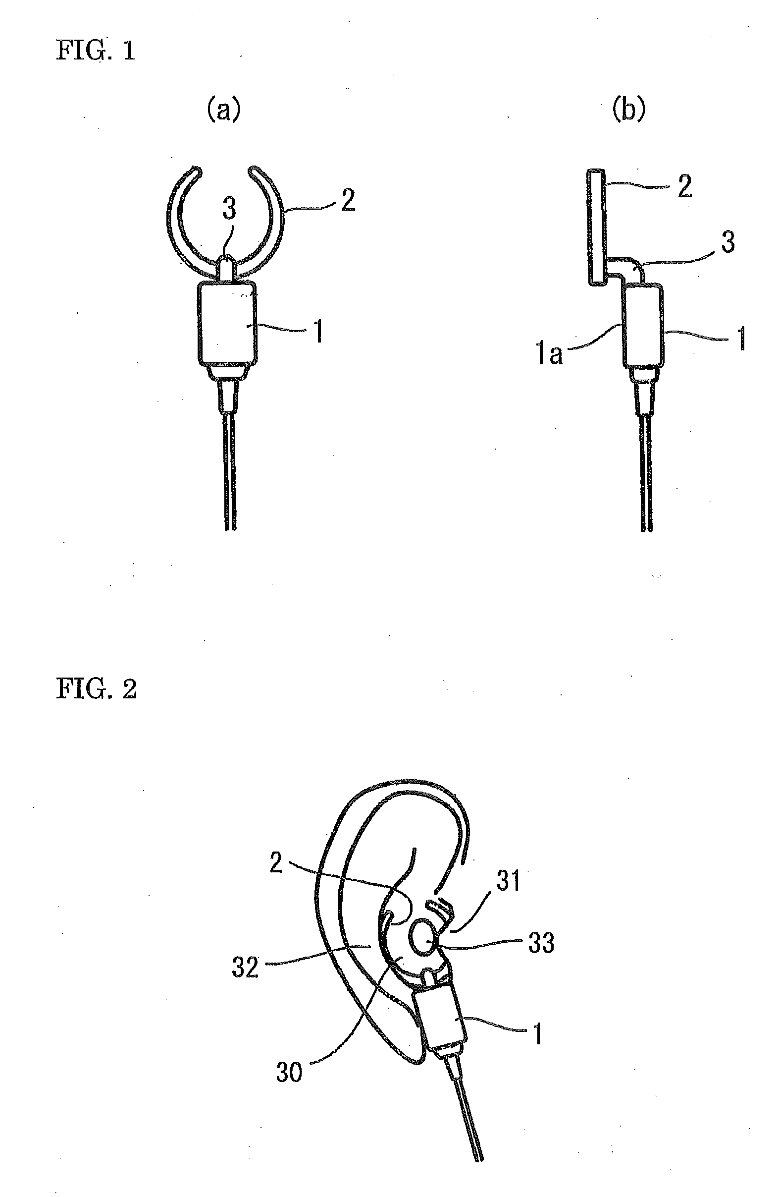
[0023]As the configuration of the holding means, various configurations can be thought of. Holding means 2 in a first embodiment shown in FIG. 1 is formed into a C shape by cutting a part of an annular ring, and the middle part thereof is fixed to the tip end of an attaching arm 3 provided on the upper surface of the speaker body 1, by which the holding means 2 is attached to the bone conductive speaker body 1.

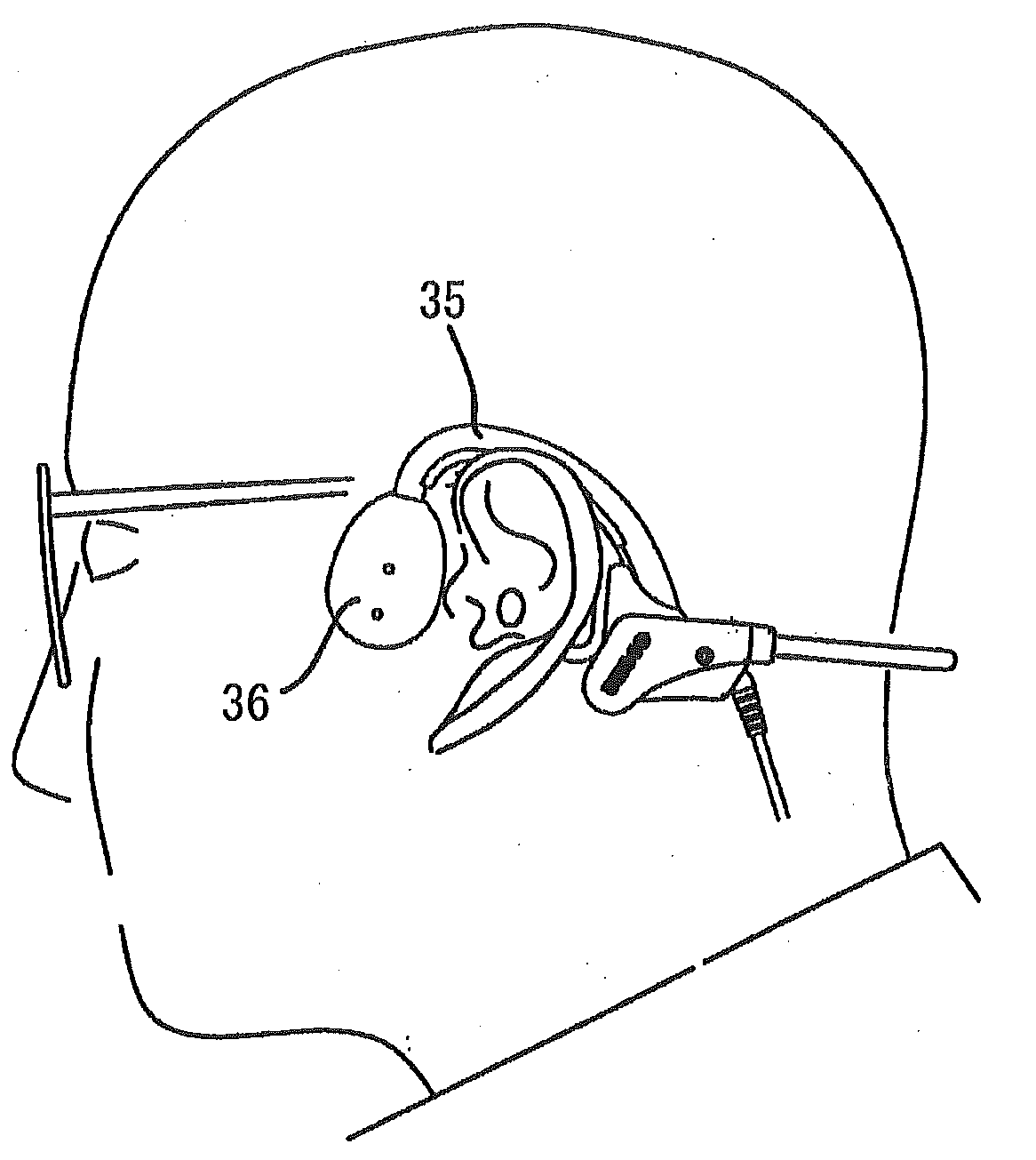
[0024]The attaching arm 3 has a right-angle shape, so that by fixing the holding means 2 at the tip end of the attaching arm 3, the holding means 2 is shifted from the axis line of the bone conductive speaker body 1 (refer to FIG. 1b). By this shift, a vibration surface 1a of the bone conductive speaker body 1 is brought into contact moderately with the tragus 31 or a portion in the vicinity thereof when the holding means 2 is accommodated in the concha cavity 30.

[0025]The holding means 2 shown in the figures is configured so that the right- and left-hand sides thereof are sym...

second embodiment

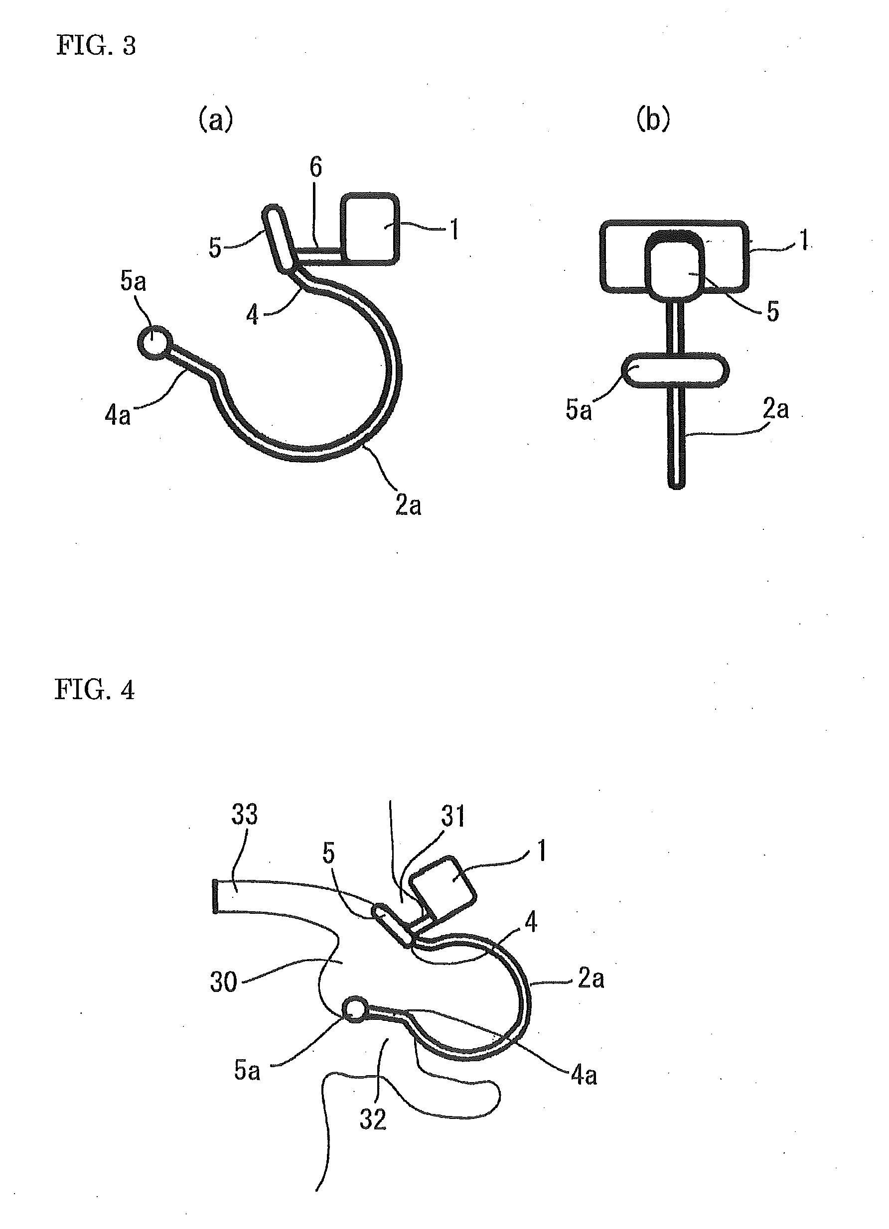
[0029]Holding means 2a in a second embodiment shown in FIGS. 3 and 4 is, like the above-described holding means 2, formed into a C shape by using a metal-made or resin-made elastic material or rigid material, and is provided with outward opening parts 4 and 4a so that both end parts of the holding means 2a are open outward. In this case, unlike in the case of the holding means 2, the bone conductive speaker body 1 is attached to one end part of the holding means 2a, in other words, to one outward opening part 4.

[0030]Although the holding means 2 in the first embodiment is put on in the vertical state, the holding means 2a in the second embodiment is put on in the horizontal state. Specifically, one outward opening part 4 comes into contact with the inside of the tragus 31, and the other outward opening part 4a comes into contact with the inside surface of the concha cavity 30 (refer to FIG. 4), and the bone conductive speaker body 1 is attached to the outward opening part 4 that com...


PUM


Abstract

A bone conductive speaker in which the hearing of external sounds is not inhibited because the earhole is not closed, the hearing efficiency is high and the sound leakage is small because the tragus portion is vibrated locally, and moreover the configuration is simple and the putting-on and taking-off operations are easy to perform. The bone conductive speaker comprises a bone conductive speaker body (1) and holding means (2) which is attached to the bone conductive speaker body (1) to hold the bone conductive speaker body (1) so that the bone conductive speaker body (1) is brought into contact with the tragus (31) or a portion in the vicinity thereof. The holding means (2) is of a ring shape having a size accommodated in the concha cavity (30), and both outside face parts thereof come into contact with the inside portion of the tragus (31) and the inside surface of the concha cavity (30) to continuously push them, by which the holding means (2) is locked at that position.

Description

FIELD OF THE INVENTION[0001]The present invention relates to bone conductive speaker. More particularly, it relates to a speaker for hearing bone conduction sounds by transmitting vibrations based on sound signals to the head bone, and especially a bone conductive speaker capable of being worn at a best suitable position without much effort and without closing the earhole, which is a hearing path for external sounds etc.BACKGROUND OF THE INVENTION[0002]As described above, the bone conductive speaker is a speaker for transmitting sounds by vibrating the head bone. When the bone conductive speaker is used, there is a need for bringing the vibration surface thereof into contact with any location on the head and maintaining this state. To meet this need, initially, a method was used in which, like the ordinary headphone, a speaker was pressed against the temple and the mastoid by using a headband. In this method, it was irksome to continuously put the headband on the head, and the weari...

Claims


Application Information

Patent Timeline
IPC IPC(8): H04R1/00
CPCH04R2460/13H04R1/1091H04R1/10H04R13/00
Inventor FUKUDA, MIKIOTAKEDA, TAKESHI
Owner TEMCO JAPAN
Why Eureka
Try Eureka