Cover Strip for a Linear Guide Rail

a technology of linear guide rails and cover strips, which is applied in the direction of linear bearings, shafts and bearings, bearings, etc., can solve the problems of poor dustproof effect, deformation and disengagement increase the cost of the cover strip, so as to reduce the manufacturing cost, the best dustproof effect, and the effect of high precision

Inactive Publication Date: 2009-11-26
HIWIN TECH
View PDF11 Cites 12 Cited by
  • Summary
  • Abstract
  • Description
  • Claims
  • Application Information

AI Technical Summary

Benefits of technology

[0016]The primary objective of the present invention is to provide a cover strip for a linear guide rail, wherein the cover strip is slantways guided along two sides of the guide rail to flanges and extends downward to cover ridges of the flanges to make the cover strip fully cover an upper surface and two side edges of the guide rail, so as to achieve the best dustproof effect.
[0017]The second objective of the present invention is to provide a cover strip for a linear guide rail, wherein two sides of the cover strip are engaged with the bottom edges of the flanges of the guide rail in such a manner that the cover strip is assuredly positioned to the flanges at two sides of the guide rail, so that the cover strip is unnecessary to have high precision but can be assuredly positioned on the slide rail, greatly reducing the manufacturing cost.
[0018]Another objective of the present invention is to provide a cover strip for a linear guide rail, wherein two sides of the cover strip bend inward to engage with the bottoms of the flanges at two sides of the guide rail in such a manner that the sharp portions of the free ends of the cover strip cannot be exposed to cut objectives or personals, thus offering high safety.
[0019]Another objective of the present invention is to provide a cover strip for a linear guide rail, wherein the cover strip has two extending portions at two sides thereof, and the angle between the respective extending portion and the central portion is greater than 90°, so that the structure body of the cover strip bends at an angle not more than 90°, thus avoiding the problem of stress concentration, increasing strength and effectively extending service life.

Problems solved by technology

1. The cost is increased due to the formation of the elongated groove;
2. Dust or dirt can still accumulate at the joint between the cover strip and the groove, so the dustproof effect is poor;
3. In a high temperature or lower temperature environment, or an environment where the temperature difference is great, the coefficient of thermal expansion and cold contraction of the cover strip is far larger than that of the groove of the guide rail, and the cover trip is clamped by the groove, so it is more likely to cause deformation and disengagement of the cover strip.
1Two sides of the cover strip are bent outward, so the resulting sharp portion is likely to cut the scraping sheet, affecting the sealing and dustproof function.
2. The intermediate section of the cover strip is engaged with the undercut portion of the guide rail via a round portion, so the cover strip and the guide rail are required to both have very high geometrical precision, causing a much higher manufacturing cost.
1. Dirt or dust may possibly collect at the undercut and then penetrates into the interior of the slide block.
2. The angle between the center section and the respective edge section of the cover strip is smaller than 90°, when the cover strip is frequently assembled and disassembled, the edge sections is likely to cause the plastic deformation, losing the effect of engagement with the guide rail.
This design has the disadvantages such as: the angle between the side edge portion and the center portion of the cover strip is 90°, and the side edge is likely to cause plastic deformation due to frequent assembly and disassembly, losing the effect of engagement with guide rail.

Method used


Image

  • Cover Strip for a Linear Guide Rail
  • Cover Strip for a Linear Guide Rail
  • Cover Strip for a Linear Guide Rail

Examples


Embodiment Construction

[0026]The present invention will be clearer from the following description when viewed together with the accompanying drawings, which show, for purpose of illustrations only, the preferred embodiment in accordance with the present invention.

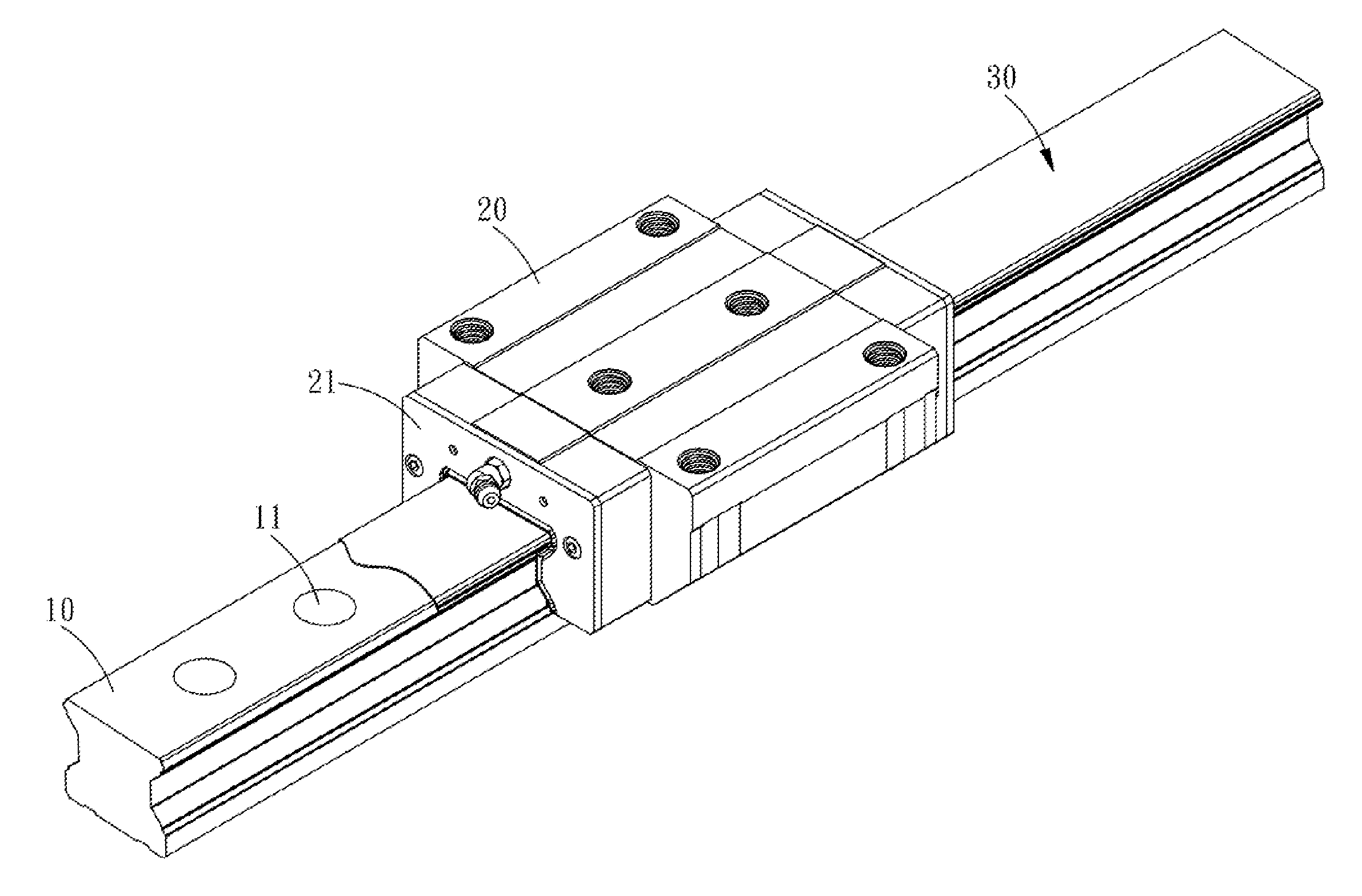
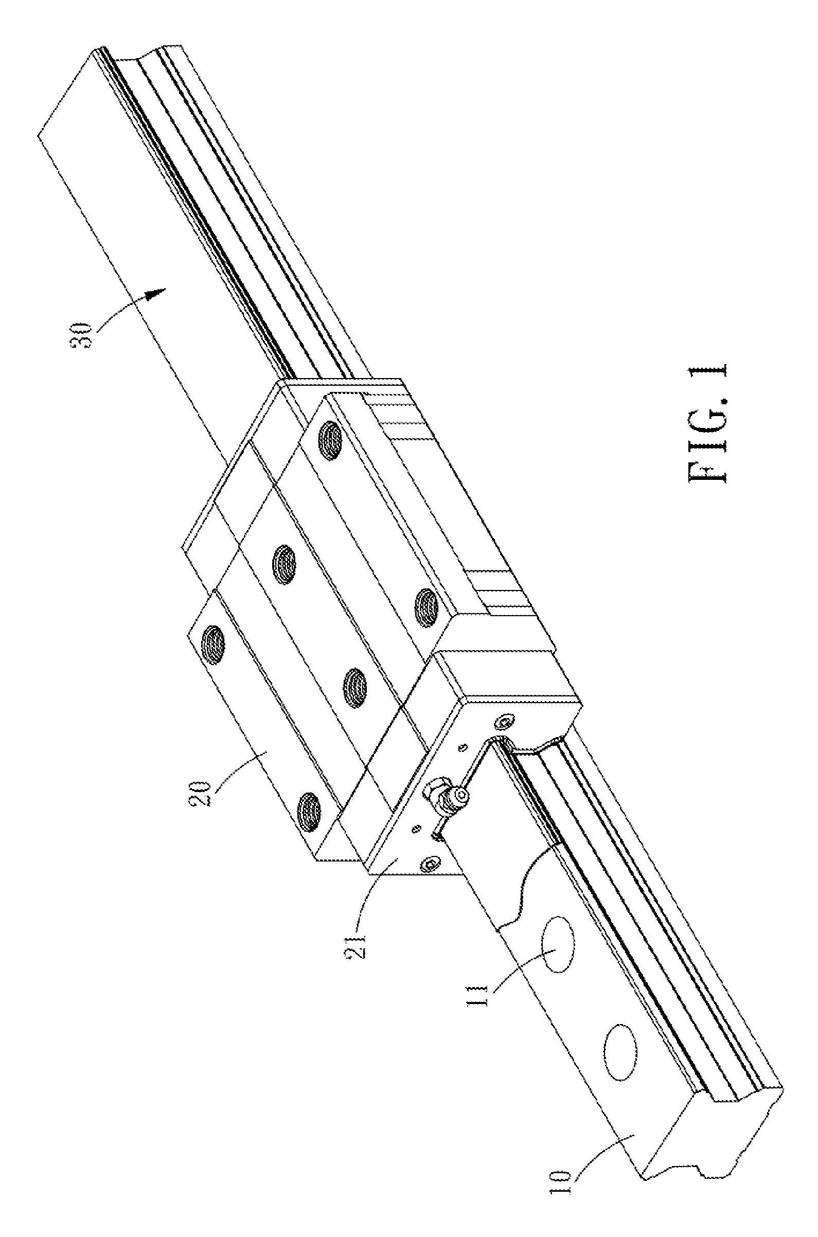
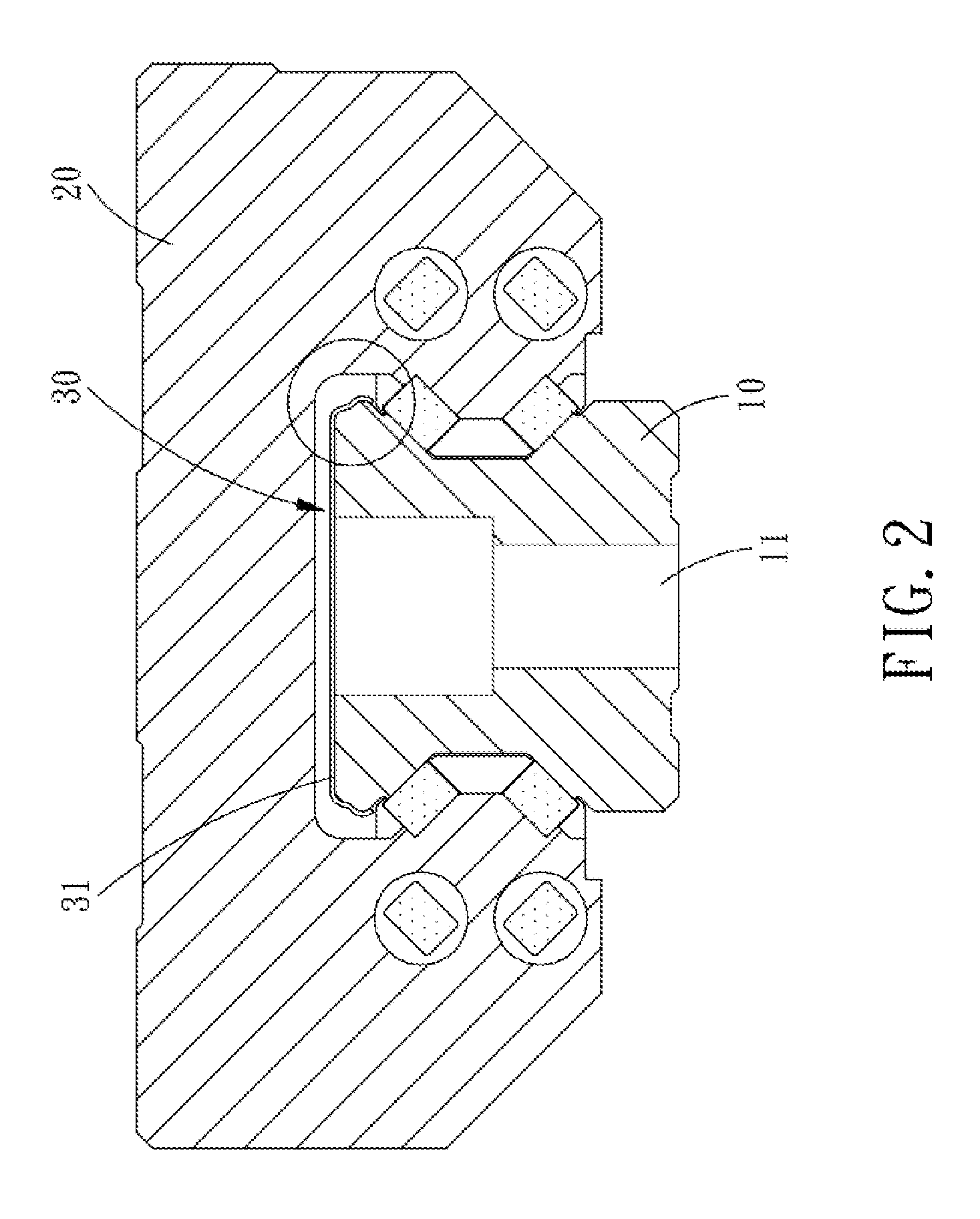
[0027]Referring to FIGS. 1-4, a slide block 20 is slidably mounted on a guide rail 10, and the guide rail 10 is provided with a plurality of bolt mounting holes 11 for insertion of bolts to fix the guide rail to a machine or other positions. The slide block 20 is provided on two ends thereof with two scraping plates 21. A cover strip 13 covers an upper surface 12 of the guide rail 10. Plural rolling elements 40 are interposed between the slide block 20 and the guide rail 10 and connected together by a retainer 41. The present invention is characterized in that, the entire cover strip 30 is configured according to the guide rail 10 and to have a predetermined engaging force for reinforcing the engagement between the cover strip 30 and the guide ra...


PUM


Abstract

A cover strip for a linear guide rail, wherein a slide block is slidably disposed on the guide rail, a cover strip covers an upper surface of the guide rail, each of two sides of the guide rail extend outwards to form an extending surface with large slope, and each extending surface extends downward to form a flange, two sides of the central portion of the cover strip are provided with extending portions, and each extending portion extends downwards to form an engaging portion, the structures extending from two sides of the cover strip are configured in the shape of the corresponding structures of the guide rail, and a free end of each engaging portion extends downward to cover the ridge of each flange in such a manner that the cover strip can be positioned on the guide rail assuredly and stably.

Description

BACKGROUND OF THE INVENTION[0001]1. Field of the Invention[0002]The present invention relates to a cover strip for a linear guide rail, and more particularly to a cover strip applied onto an upper surface of a linear guide rail, which can be engaged to the guide rail more assuredly and conveniently and has the advantages such as better dustproof effect and lower cost.[0003]2. Description of the Prior Art[0004]In order to improve the dustproof effect, guide rails for the linear guideways are each provided with a cover strip on the upper surface thereof. The existing guide rails, as disclosed in U.S. Pat. No. 6,012,846, U.S. Pat. No. 6,502,988, U.S. Pat. No. 6,629,779, U.S. Pat. No. 6,749,338, etc are each formed with an elongated groove in the upper surface thereof, and the cover strip is fixed to two inner sides of the groove. Such a design has the following disadvantages:[0005]1. The cost is increased due to the formation of the elongated groove;[0006]2. Dust or dirt can still accu...

Claims


Application Information

Patent Timeline
Patent Type & Authority Applications(United States)
IPC IPC(8): F16C29/08
CPCF16C29/082F16C29/065
Inventor CHEN, TSUNG-JEN
Owner HIWIN TECH
Why Eureka
Try Eureka