
Trash container emptying mechanism

a technology for emptying mechanisms and trash containers, applied in the field of containers, can solve problems such as health problems, industrial insurance costs, and the removal of the trash container liner

Active Publication Date: 2009-11-26
HOPKINS DALE
View PDF22 Cites 6 Cited by
  • Summary
  • Abstract
  • Description
  • Claims
  • Application Information

AI Technical Summary

Benefits of technology

[0018]a principal object to provide a trash container emptying apparatus that eliminates the need to lift a trash container liner vertically out of the trash container.
[0022]a further object to provide such an apparatus that may be pivoted to ease removal of a filled trash container liner from the trash container
[0027]a still further object to provide such an apparatus that reduces the risk of worksite and industrial injuries.

Problems solved by technology

Because the trash containers are commonly industrial size “Rubber Maid®” type trash containers, and because the trash container is raised an additional distance above the supporting ground surface by the cart wheels, removing the trash container liner can be difficult and is a frequent cause of industrial injuries such as back strains, pulled muscles and sprained shoulders leading to health problems and industrial insurance costs.
There are known devices that assist in the removal of trash container liners from trash containers, but such devices have various drawbacks including they are not mountable to existing janitorial carts, they are not adaptable to standard trash containers, the trash container is integrally built into the device, they are not readily mobile and they require a user to lift the entire weight of the trash container and material contained therein to empty the container among other drawbacks.

Method used


Image

  • Trash container emptying mechanism
  • Trash container emptying mechanism
  • Trash container emptying mechanism

Examples


Embodiment Construction

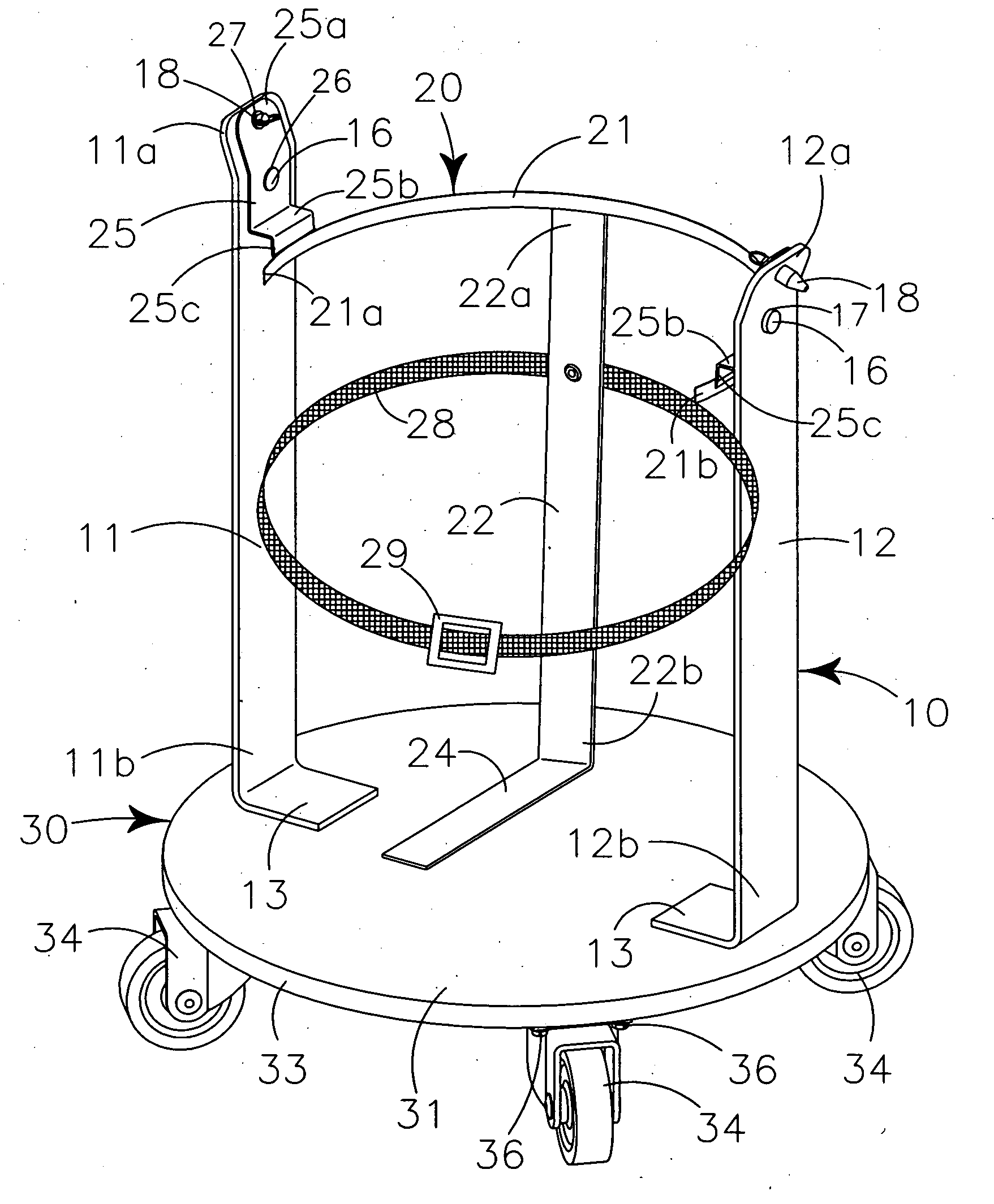
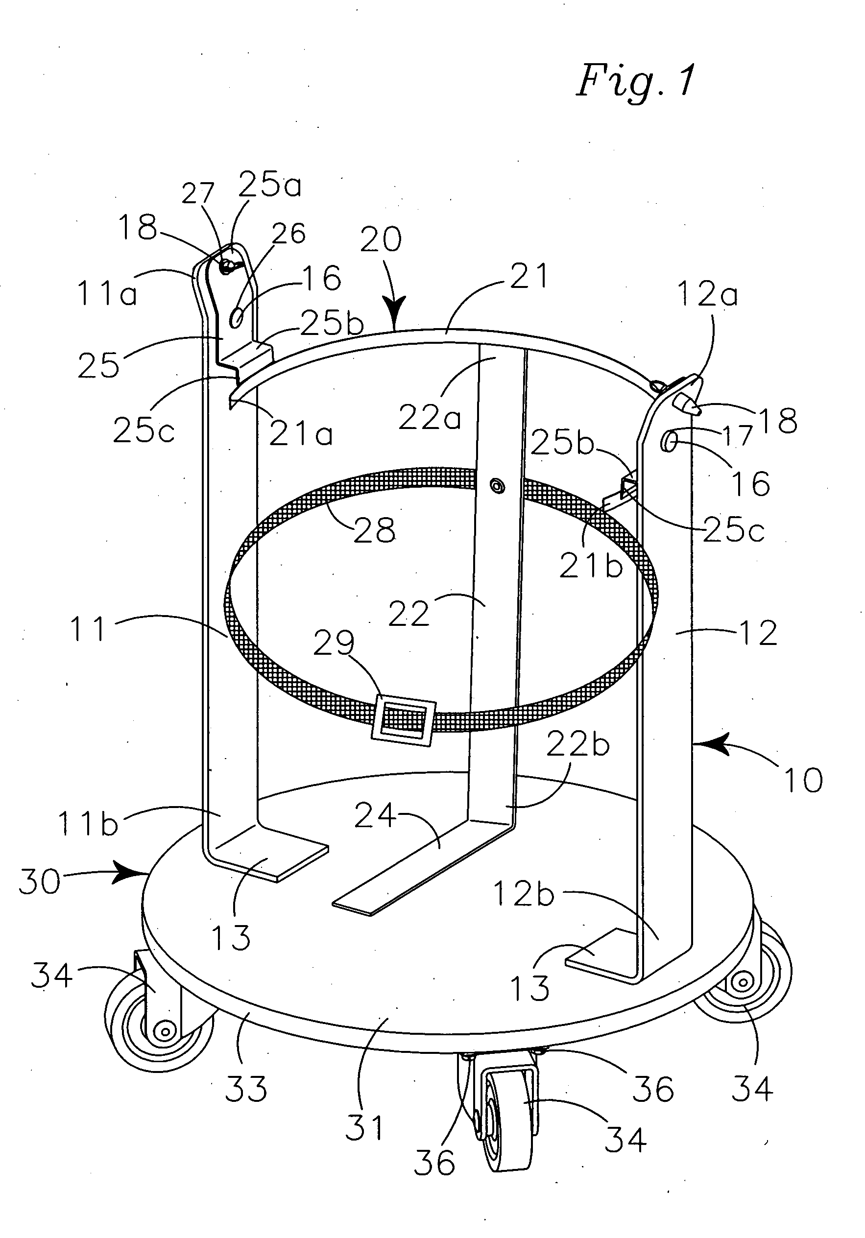
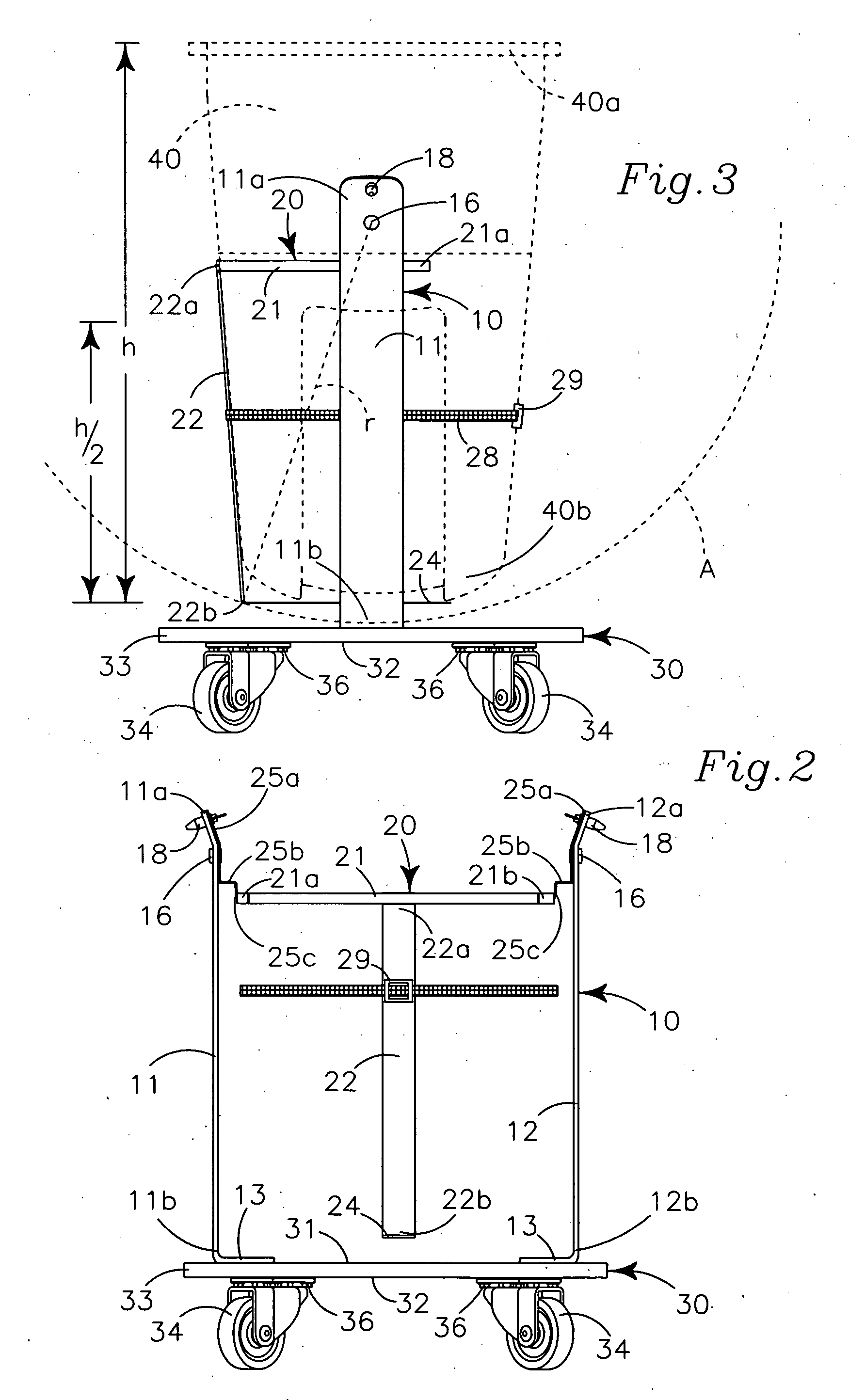
[0037]My trash container emptying mechanism provides an upstanding “U” shaped yoke 10 supporting a pivotal trash container carrier 20 and mounted to a wheeled cart 30.

[0038]The upstanding “U” shaped yoke 10 is formed of a strong, rigid and durable material such as galvanized steel or high density polyethylene plastic and has two horizontally spaced apart vertically extending arms 11, 12 each arm having an upper end portion 11a, 12a and an opposing lower end portion 11b, 12b.

[0039]The upper end portion 11a, 12a of each vertical arm 11, 12 defines an axle hole 17 and a locking pin hole 19.

[0040]A perpendicular base portion 13 at the lower end portion 11b, 12b of each arm 11, 12 defines plural spacedly arrayed fastener holes (not shown) for fasteners (not shown) extending therethrough to secure the vertical arm 11, 12 to the wheeled cart 30.

[0041]As shown in FIG. 1, each vertically extending yoke arm 11, 12 may have a perpendicular base portion 13 that is mounted to the wheeled cart 3...


PUM


Abstract

A trash container emptying mechanism provides an upstanding “U” shaped yoke with two horizontally spaced apart vertically extending arms each having a perpendicular base portion mounted to wheeled cart. A trash container carrier having a partially circumferentially extending rigid upper support, a vertically spaced apart bottom support and at least one vertical leg communicating between the rigid upper support and the bottom support is pivotally carried within the yoke on two offset pivot spacers and two horizontal axles extending therethrough and therebetween. A flexible length adjustable strap releasably secures the trash container to the carrier and a removable position locking pin extends through aligned axle holes defined in yoke vertical arm and carrier to positionally secure the carrier and trash container in a vertical orientation within the yoke.

Description

RELATED APPLICATIONS[0001]There are no applications related hereto heretofore filed in this or in any foreign country.BACKGROUND OF INVENTION[0002]1. Field of Invention[0003]This invention relates to containers, and more particularly to a trash container carrying mechanism that can be optionally pivoted about a horizontal axis to ease emptying the trash container.[0004]2. Background and Description of Prior Art[0005]Emptying trash containers is a daily task for many persons especially those involved in the janitorial trade who clean offices, schools, cafeterias and other places where people work and congregate. In the course of such work, persons frequently move a wheeled cart from office to office or location to location. The wheeled cart commonly carries various cleaning tools and supplies and also carries a large trash container into which the contents of smaller trash containers are emptied. Typically the cart is supported on plural spacedly arrayed caster-type wheels which rais...

Claims


Application Information

Patent Timeline
Patent Type & Authority Applications(United States)
IPC IPC(8): B65F3/02
CPCB65F1/12B65F1/1468B65F1/141
Inventor HOPKINS, DALE
Owner HOPKINS DALE
Learn More