Air Curtain Doorway With Integrated Doors

a technology of air curtain and doorway, which is applied in the direction of static/dynamic balance measurement, shutters/movable grilles, instruments, etc., can solve the problems of repeated operation, inability to provide insulation, and inability to meet the needs of air doors, so as to minimize the mixing of zoned air, improve the efficiency and ease of passage of air doors, and improve the effect of insulating barrier

Inactive Publication Date: 2009-11-26
ASI TECH
View PDF6 Cites 12 Cited by
  • Summary
  • Abstract
  • Description
  • Claims
  • Application Information

AI Technical Summary

Benefits of technology

[0011]The present invention, in one embodiment, comprises an air door sandwiched between a pair of roll-up doors. The invention provides the efficiency and ease of passage of an air door during peak passage times and the ability to deploy the roll-up doors to minimize mixing of the zoned air during off-peak times and provide a more positive insulative barrier between the two zones, and also a barrier to passage. The integration of an air door and a pair of roll-up doors creates a redundant insulation system between zones. If the air door fails, both roll-up doors can be deployed to maintain an insulating layer of air sandwiched between the zones. Alternatively, if the roll-up doors fail, or are left in the retracted position, the air curtain maintains an thermally insulative barrier between the zones.

Problems solved by technology

Roll-up doors provide no insulation between zones when retracted and when down impede passage.
Repeated operation also can take a mechanical toll on the components of the roll-up door, and although operation is quite rapid, it still does take some time.
This air exchange is costly; leaving air-conditioning equipment to compensate for the exchange, costing time and energy.
An air curtain exchanges air with the adjacent zones between which it is installed and in doing so can put an added load on the refrigeration system of the cold zone, or under some conditions can result in an undesirable formation of frost around the doorway if it draws in warm moist air from the warmer zone and cools it or blows it into the refrigerated zone.
Also, running the air mover (e.g., electric fan) non-stop may not at times be the most efficient way to insulate between different zones during periods where passage between the zones is minimal, especially where the climatic differential is large between the adjacent zones.

Method used


Image

  • Air Curtain Doorway With Integrated Doors
  • Air Curtain Doorway With Integrated Doors
  • Air Curtain Doorway With Integrated Doors

Examples


Embodiment Construction

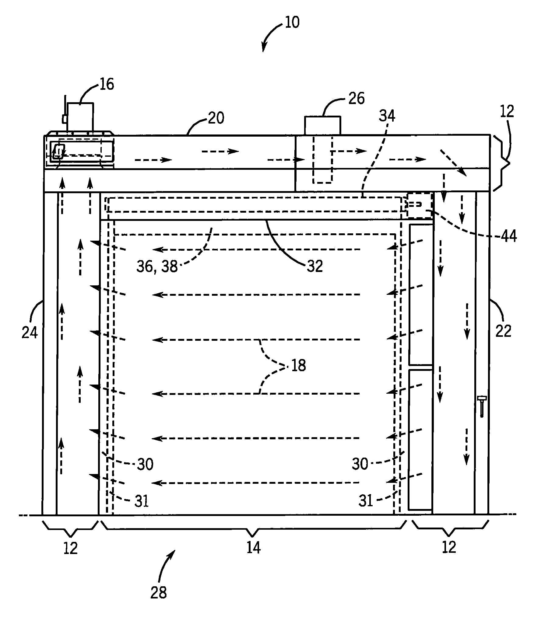
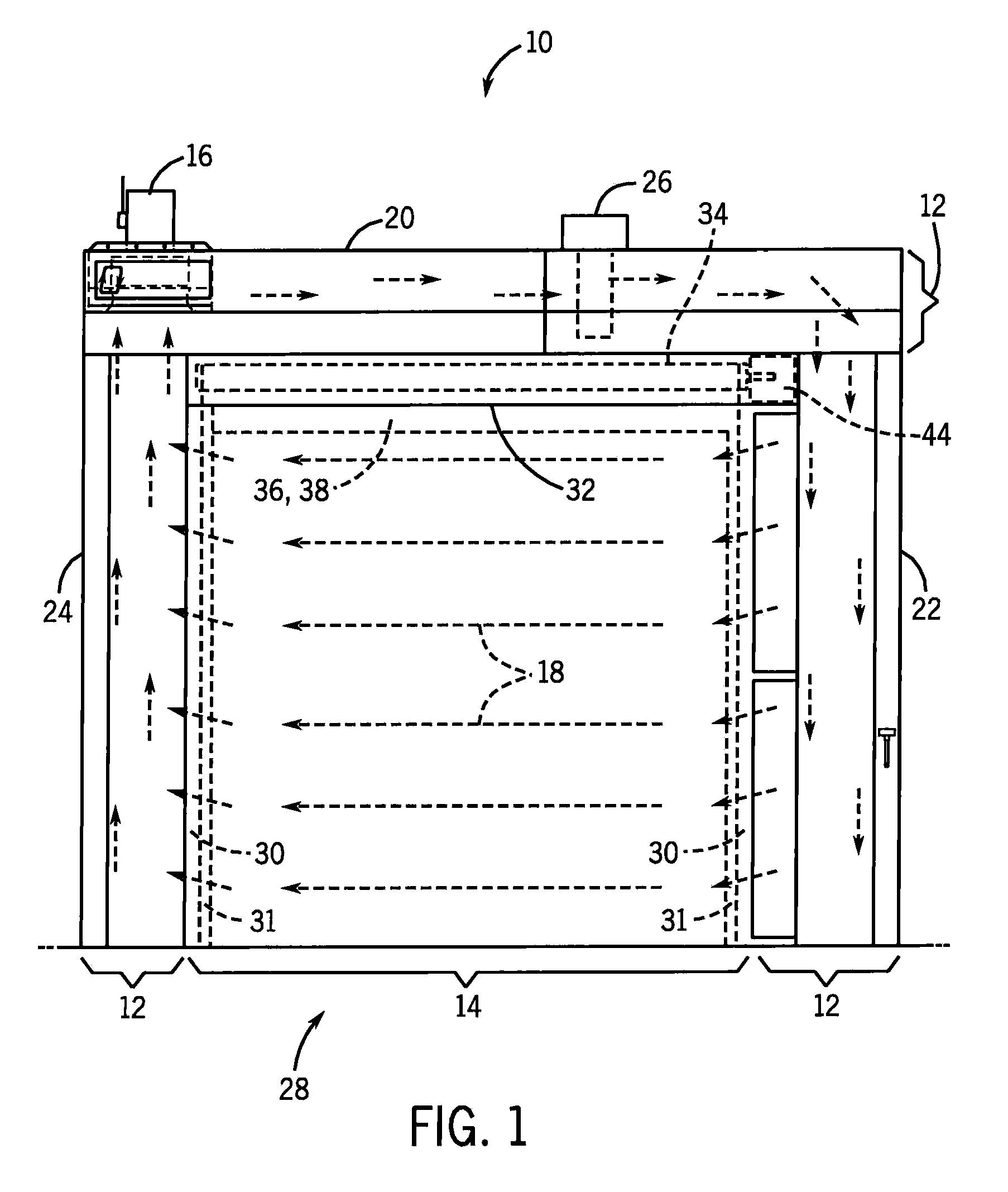
[0021]An air curtain doorway with integrated doors is generally designated by reference numeral 10 in FIG. 1. The doorway 10 includes two main portions, an outer air curtain assembly 12 and a door assembly 14. The structure and inter-operation of each portion is discussed in detail below.

Air Curtain Assembly

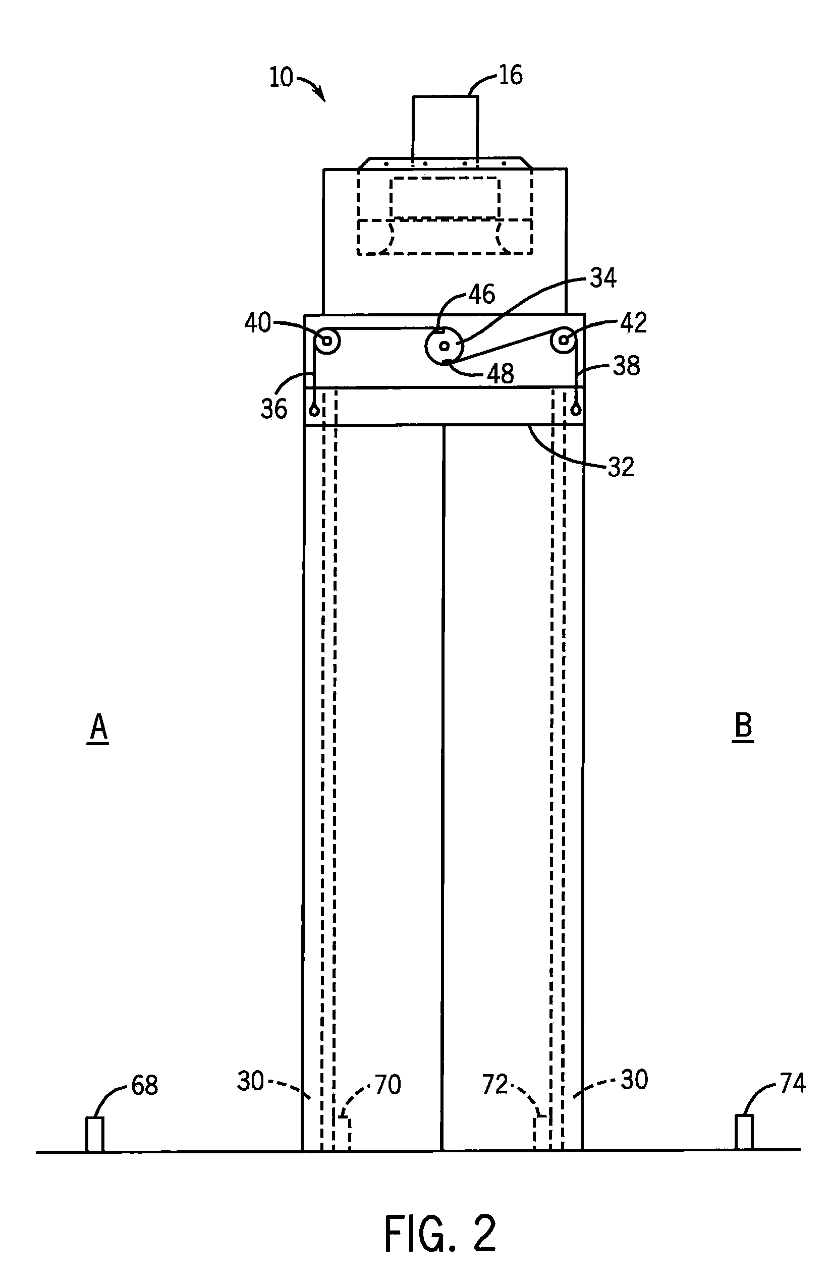
[0022]The air curtain assembly 12, shown in FIG. 1, uses a series of joined ducts 20, 22, 24 and an air mover 16 to create an air curtain 18. The air curtain 18 is generally used to separate areas, or zones, having differing climatic properties (e.g., temperature, humidity). As shown in FIG. 2, the doorway 10 is disposed between a first zone A and a second zone B. The air curtain 18 may be created to travel from right to left (as shown in the present embodiment for illustrative purposes), left to right, top to bottom, bottom to top, or any variation thereof. The disclosure of U.S. Pat. No. 6,595,429 of an air curtain and the control of an air curtain that may be used for the air ...


PUM


Abstract

An air curtain doorway defining an opening between at least two zones, including an air curtain having an air supply duct and an air return duct joined by a connecting duct. A frame having spaced apart jambs connected at the top by a header is configured to fit substantially within the opening of the air curtain. At least two roll-up doors in communication with the frame are configured to selectively insulate the at least first and second zones. A method of controlling a plurality of roll-up doors of an air curtain doorway comprises the steps of monitoring the output of at least a first sensor and a second sensor to sense approach of the doorway, applying logic to the output of the sensors, and controlling at least one of the doors based upon the result of the applied logic. The method can also include closing the roll-up doors while the air curtain is blowing, or turning off the air curtain and closing the roll-up doors.

Description

CROSS-REFERENCE TO RELATED APPLICATIONS[0001]This application claims priority to U.S. Provisional Application No. 61 / 054,517 filed May 20, 2008.STATEMENT REGARDING FEDERALLY SPONSORED RESEARCH OR DEVELOPMENT[0002]Not applicable.FIELD OF THE INVENTION[0003]This invention relates to air curtains, and more particularly, to an air curtain doorway incorporating a plurality of doors for insulating the air curtain.BACKGROUND OF THE INVENTION[0004]Many facilities have discrete areas wherein each area is maintained at a different climatic condition relative to an adjacent area. These segregated areas, or zones, occur at locations such as the interface between a loading dock and a storage facility. The loading dock may be located outdoors and therefore subject to the elements, while the storage facility may be in an environmentally controlled zone to ensure the integrity of the stored product and relative comfort of the personnel. Other facilities may have a large interior refrigeration zone ...

Claims


Application Information

Patent Timeline
Patent Type & Authority Applications(United States)
IPC IPC(8): F24F9/00E06B3/32G05B15/00
CPCF24F9/00
Inventor ZIMMERMANN, CHARLES A.BALBACH, GEORGE F.
Owner ASI TECH
Why Eureka
Try Eureka