

Ultrasonic diagnostic apparatus
- Summary
- Abstract
- Description
- Claims
- Application Information
AI Technical Summary
Benefits of technology
Problems solved by technology
Method used
Image

Examples
embodiment 1
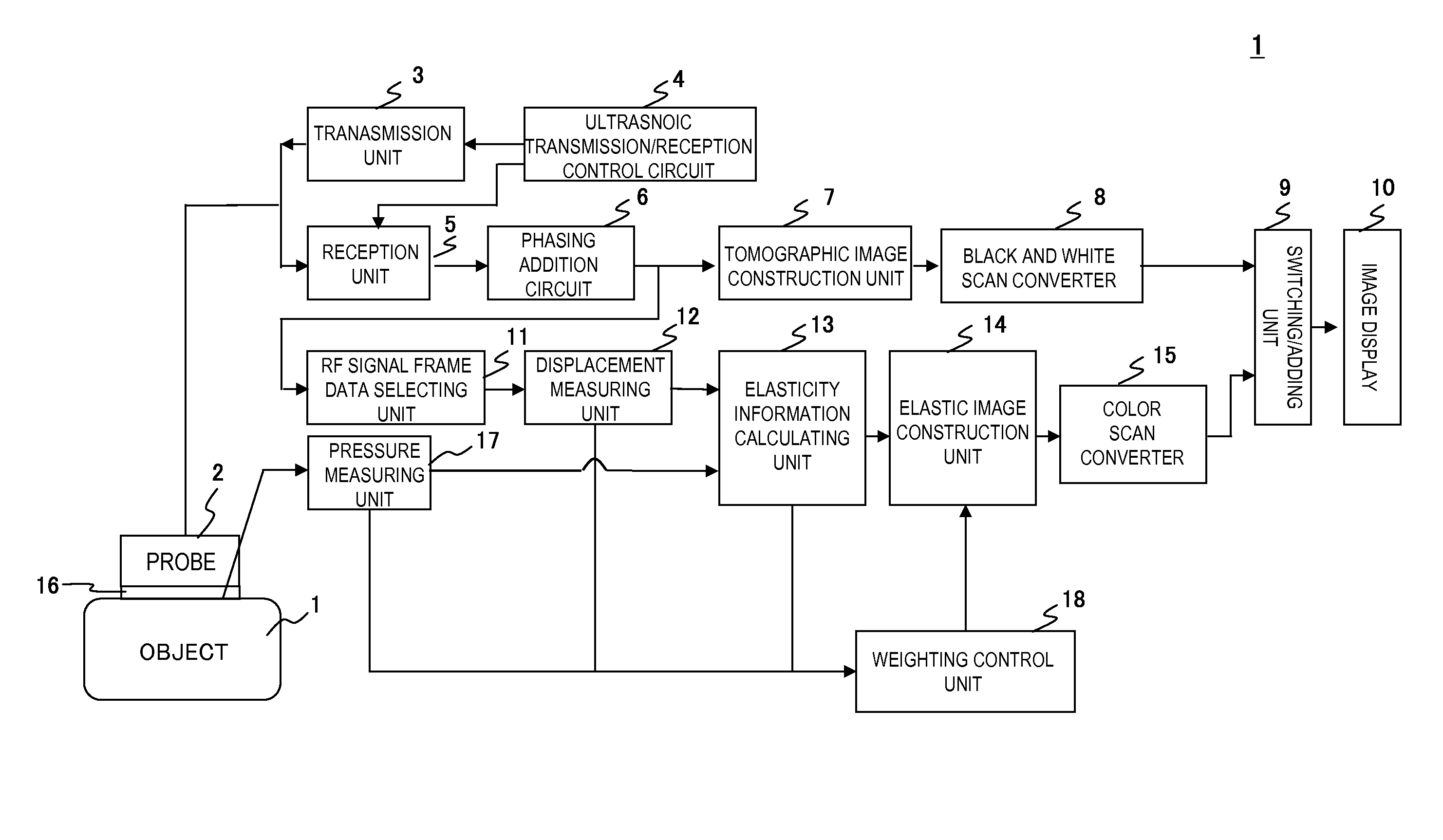
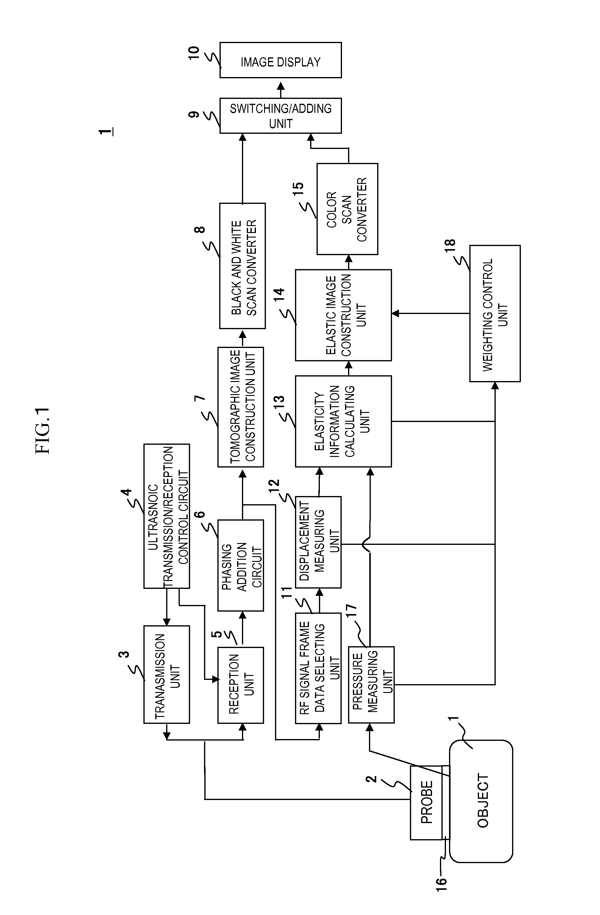
[0029]FIG. 1 is a block configuration diagram of the first embodiment related to the ultrasonic diagnostic apparatus of the present invention.
[0030]As shown in FIG. 1, an ultrasonic probe 2 for applying to an outer surface of the object 1 is configured having an ultrasonic transmitting / receiving surface in which a plurality of transducers are arranged for transmitting / receiving ultrasonic waves to / from the object 1. The ultrasonic probe 2 is connected to a transmission unit 3, and the transmission unit 3 provides ultrasonic pulses to the probe 2 for driving the probe 2. An ultrasonic transmission / reception control circuit 4 is connected to the transmission unit 3 and a reception unit 5 to be described later, and the ultrasonic transmission / reception control circuit 4 controls transmission timing of ultrasonic pulses for driving a plurality of transducers in the probe 2 to form ultrasonic beams toward a focal point to be set in an object 1. The ultrasonic transmission / reception circu...
embodiment 2
[0071]Next, a second embodiment of the ultrasonic diagnostic apparatus related to the present invention will be described using the diagrams.
[0072]Here, the second embodiment will be described referring to FIG. 5. The second embodiment is different from the first embodiment in the point that weighting or adjustment of the number of data sets for addition is performed using positional information or moving information of the probe 2 caused by compression, using a sensor such as a magnetic sensor 28.
[0073]As shown in FIG. 5a, the magnetic sensor 28 for detecting magnetic field is mounted in the probe 2 and detects high-frequency magnetic field irradiated from a magnetic field source 29. A position / direction analyzing unit which is not shown in the diagram is for obtaining the position or direction of the magnetic field sensor 28, that is probe 2 on the basis of the magnetic field source 29 by analyzing the magnetic detection signals detected by the magnetic field sensor 28 in the cond...
embodiment 3
[0079]Here, a third embodiment will be described referring to FIG. 6. The difference from the first˜second embodiments is to optimize the weighting of elasticity frame data to add and the number of sets of data for the addition, by the frame rate for obtaining RF signals. In the present embodiment, two sets of frame data are weighted and added in accordance with the frame rate, or more than three sets of elasticity frame data are to be weighted and added.
[0080]For example, when the frame rate is high, since the displacement to be measured in the displacement measuring unit 12 is minimal, there are cases that it is difficult to measure the strain in the elasticity information calculating unit 13. This could lead to causing many errors or artifacts in the plurality of elasticity frame data. Therefore, there is a need for adding many sets of elasticity frame data to output as elastic image data, in order to reduce the influence of errors or artifacts.
[0081]Given this factor, in the pre...
PUM
 Abstract
Description
Claims
Application Information