Method for Inserting a Catheter

a catheter and assembly technology, applied in the direction of multi-lumen catheters, trocars, ear treatment, etc., can solve the problems of impracticality of tunneling after the catheter is installed in the patient, failure of catheter external parts of the patient, and only possible techniques

Inactive Publication Date: 2009-11-26
TWINCATH +1
View PDF52 Cites 29 Cited by
  • Summary
  • Abstract
  • Description
  • Claims
  • Application Information

AI Technical Summary

Benefits of technology

[0009]Briefly, the present invention provides a multiple catheter assembly. The assembly includes a first catheter constructed from a first material and having a first proximal end region, a first distal end region terminating in a first distal tip, and an outer surface defining at least a first lumen extending longitudinally therethrough between a first distal and a first proximal opening. The first proximal end region is integrally connected to an extension tube constructed from a second material. A second catheter is constructed from the first material and having a second proximal end region, a second distal end region terminating in a second distal tip, and a second outer surface defining at least a second lumen extending longitudinally therethrough between a second distal and a second proximal opening. The second proximal end region is integrally connected to an extension tube constructed from the second material. The first and second lumens are independent from each other for facilitating simultaneous flow in opposite directions. The outer surfaces of the first and second catheters are releasably joined for allowing the first and second distal tips to be at least partially longitudinally split from each other.
[0010]Further, the present invention also provides a method for inserting a multiple catheter assembly into an area of a body to be catheterized. The method comprises: making an incision near the area to be catheterized; and providing a multiple catheter assembly comprising a first catheter constructed from a first material and having a first proximal end region, a first distal end region terminating in a first distal tip, and an outer surface defining at least a first lumen extending longitudinally therethrough between a first distal and a first proximal opening. The first proximal end region is integrally connected to an extension tube constructed from a second material. The catheter also comprises a second catheter constructed from the first material and having a second proximal end region, a second distal end region terminating in a second distal tip, and a second outer surface defining at least a second lumen extending longitudinally therethrough between a second distal and a second proximal opening. The second proximal end region is integrally connected to an extension tube constructed from the second material. The first lumen and the second lumens are independent from each other for facilitating simultaneous flow in opposite directions. The outer surfaces of the first and second catheters are releasably joined for allowing the first and second distal tips to be at least partially longitudinally split from each other. The method further comprises at least partially separating the first and second distal end regions of the first and second catheters from each other; and inserting the first and second distal end regions of the first and second catheters in juxtaposed relation to each other through the incision and into the area to be catheterized.
[0011]Additionally, the present invention also provides a multiple catheter assembly, comprising a first catheter constructed from a first material and has a first proximal end region, a first distal end region terminating in a first distal tip, and an outer surface defining at least a first lumen extending longitudinally therethrough between a first distal and a first proximal opening. The first lumen has a first cross-sectional shape and the first distal opening has a second cross-sectional shape. A first extension tube is integrally connected to the first proximal end region, wherein the first extension tube is constructed from a second material. A first connector is releasably connected to a proximal end of the first extension tube. A second catheter is constructed from the first material and has a second proximal end region, a second distal end region terminating in a second distal tip, and a second outer surface defining at least a second lumen extending longitudinally therethrough between a second distal and a second proximal opening. The second lumen has the first cross-sectional shape and the second distal opening has a third cross-sectional shape. The second catheter is bonded to the first catheter along a length. A second extension tube is integrally connected to the second proximal end region, wherein the second extension tube is constructed from the second material. A second connector is releasably connected to a proximal end of the second extension tube. A fabric cuff is attachable to the first and second catheters at a position along the length. The first and second lumens are independent from each other for facilitating simultaneous flow in opposite directions.
[0012]Additionally, the present invention provides a multiple catheter assembly, comprising a first catheter constructed from a first material and having a first proximal end region, a first distal end region terminating in a first distal tip, and an outer surface defining at least a first lumen extending longitudinally therethrough between a first distal and a first proximal opening. The first lumen has a first cross-sectional shape and the first distal opening has a second cross-sectional shape. A first extension tube is fixedly connected to the first proximal end region, wherein the first extension tube is constructed from a second material. A first connector is connected to a proximal end of the first extension tube. A second catheter is constructed from the first material and has a second proximal end region, a second distal end region terminating in a second distal tip, and a second outer surface defining at least a second lumen extending longitudinally therethrough between a second distal and a second proximal opening. The second lumen has the first cross-sectional shape and the second distal opening has a third cross-sectional shape. The second catheter is bonded to the first catheter along a length. A second extension tube is fixedly connected to the second proximal end region, wherein the second extension tube is constructed from the second material. A second connector is connected to a proximal end of the second extension tube. A fabric cuff is attachable to the first and second catheters at a position along the length. The first and second lumens are independent from each other for facilitating simultaneous flow in opposite directions.
[0013]Additionally, the present invention provides a multiple catheter assembly, comprising a first catheter constructed from a first material and having a first proximal end region, a first distal end region terminating in a first distal tip, and an outer surface defining at least a first lumen extending longitudinally therethrough between a first distal and a first proximal opening. The first lumen has a first cross-sectional shape and the first distal opening has a second cross-sectional shape. The catheter assembly also includes a second catheter constructed from the first material and having a second proximal end region, a second distal end region terminating in a second distal tip, and a second outer surface defining at least a second lumen extending longitudinally therethrough between a second distal and a second proximal opening. The second lumen has the first cross-sectional shape and the second distal opening has a third cross-sectional shape. The second catheter is bonded to the first catheter along a length. The first and second lumens are independent from each other for facilitating simultaneous flow in opposite directions. The first and second distal end regions are releasably joined for allowing the first and second distal end regions to be at least partially longitudinally split from each other.

Problems solved by technology

However, this technique is only possible in cases where the catheter is of a relatively small diameter, made of a stiff material, and not significantly larger than the guide wire, for example, for insertion of small diameter dual lumen catheters.
For some catheters, though, such as multiple lumen catheters with a hub and with bonded luers on the proximal ends of the catheters, it is impractical to perform the tunneling after the catheter is installed in the patient.
Further, for chronically installed catheters, portions of the catheter external to the patient occasionally fail, such as for instance, by leaking and / or by the introduction of foreign particles such as dirt, bacteria, and the like into the catheter, necessitating removal of the entire catheter from the patient.
Such failures include worn or broken clamps or broken luers.
In order to correct these problems, it is presently necessary to remove the entire catheter from the patient, causing additional trauma to the patient and risking additional medical problems to the patient.

Method used


Image

  • Method for Inserting a Catheter
  • Method for Inserting a Catheter
  • Method for Inserting a Catheter

Examples


Embodiment Construction

[0040]In the drawings, like numerals indicate like elements throughout. Certain terminology is used herein for convenience only and is not to be taken as a limitation on the present invention. The terms “distal” and “proximal” refer, respectively, to the directions “away from” and “closer to” the surgeon inserting the catheter into a patient. The terminology includes the words above specifically mentioned, derivatives thereof, and words of similar import.

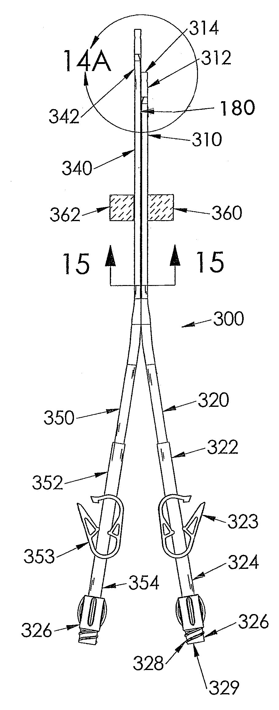
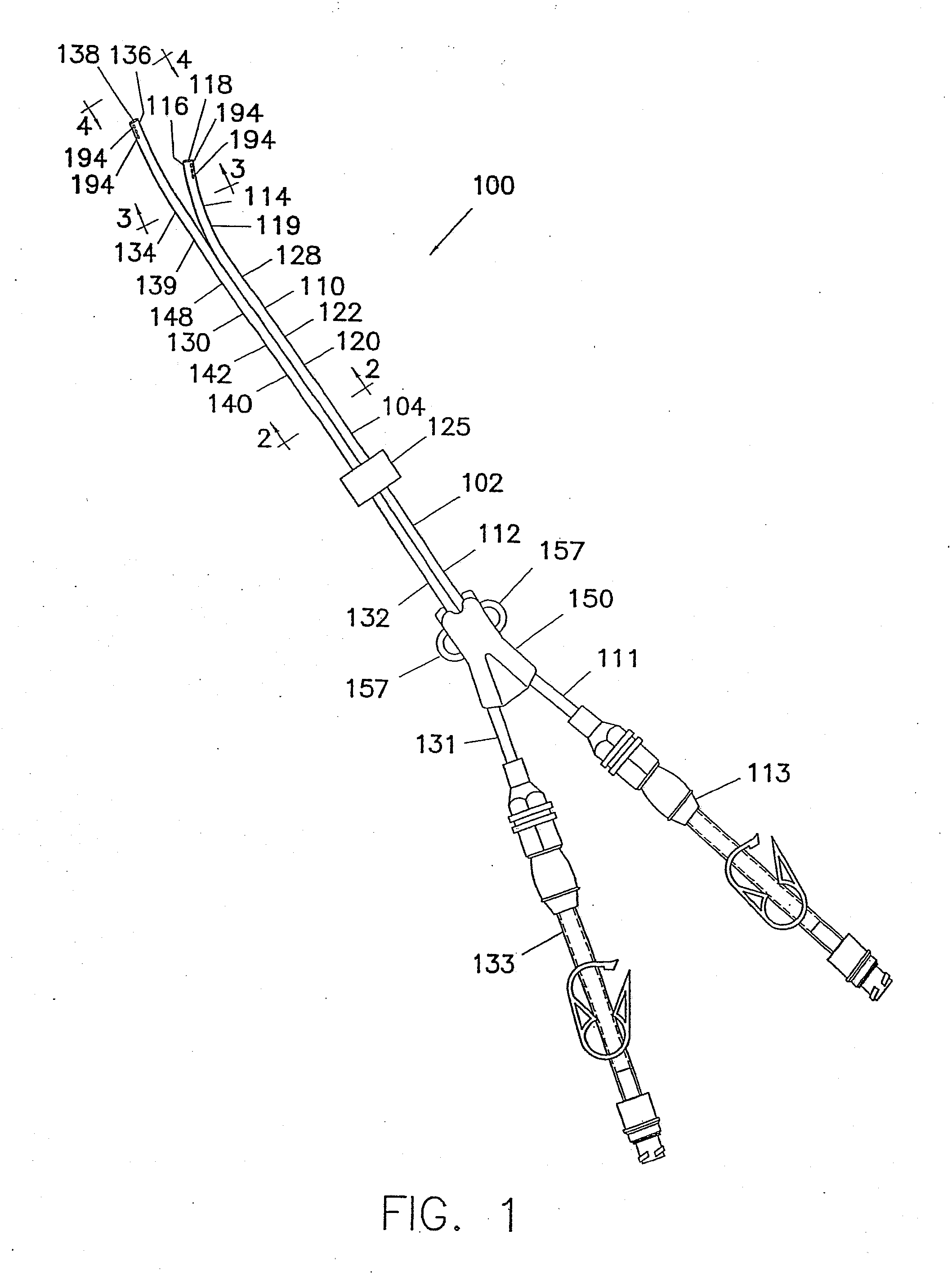
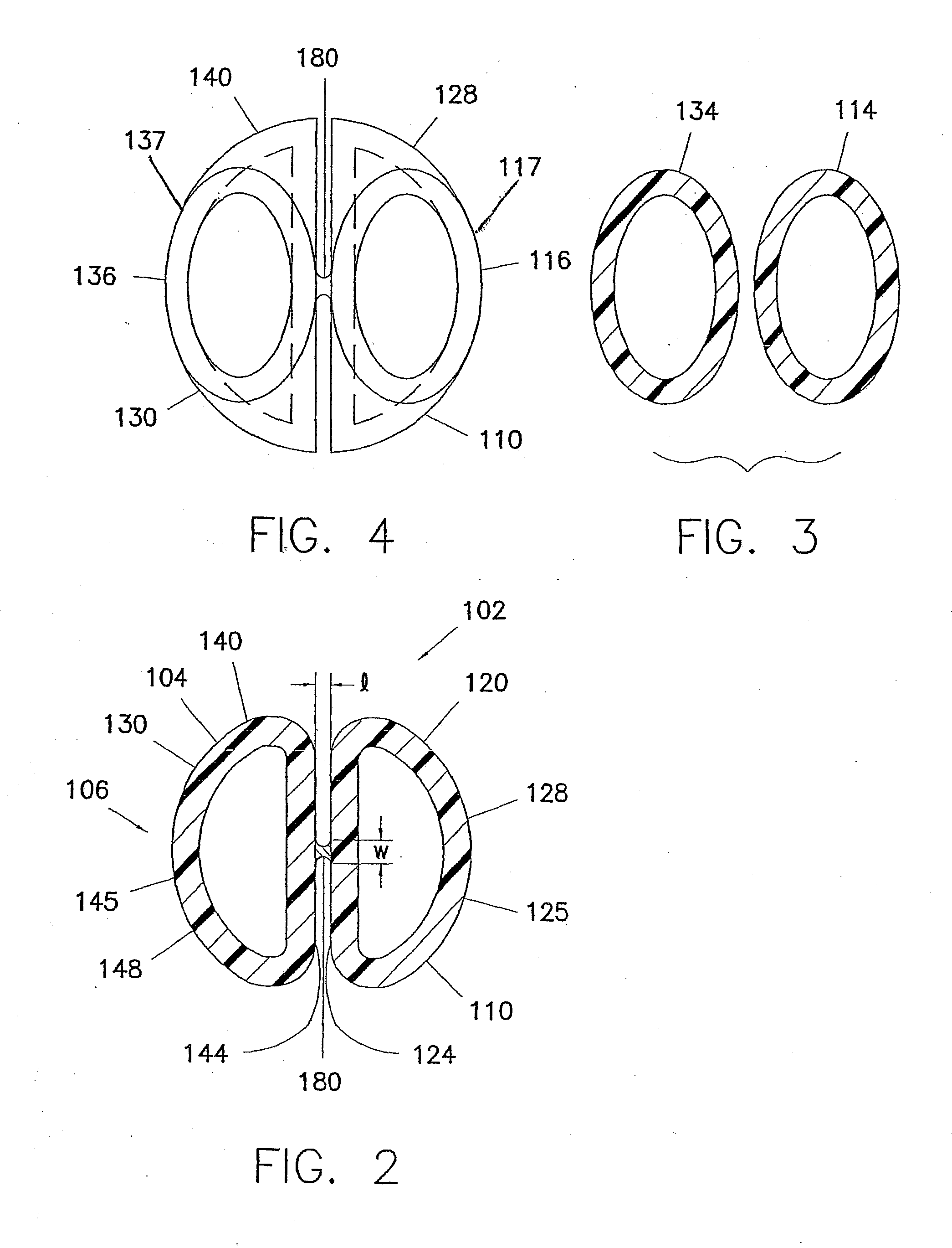
[0041]The following describes preferred embodiments of the invention. However, it should be understood, based on this disclosure, that the invention is not limited by the preferred embodiments described herein. Referring now to the drawings in detail, there is shown in FIG. 1, an embodiment of a multiple catheter assembly generally indicated as 100. The multiple catheter assembly 100 shown in FIG. 1 is a double catheter assembly, although assemblies having two or more catheters are within the scope of this invention.

[0042]The invent...


PUM


Abstract

A method for inserting a multiple catheter assembly into a patient. The assembly (100) includes a first catheter (110) having a first distal end region (114) and an outer surface (120) defining at least a first lumen (122). A second catheter (130) has a second distal end region (134) and a second outer surface (140) defining at least a second lumen (142) The outer surfaces (120,140) of the first and second catheters are releasably joined by a splittable bond (180) for allowing the first and second distal tips (116,136) to be at least partially longitudinally split from each other. The method includes the steps of separating the first and second distal end regions, and inserting the first and second distal end regions in juxtaposed relation to each other through the incision and into the area to be catheterized.

Description

CROSS-REFERENCE TO RELATED APPLICATIONS[0001]The present application is a Divisional of U.S. patent application Ser. No. 10 / 947,267, filed Oct. 24, 2004, which is a Continuation-in-Part of U.S. patent application Ser. No. 10 / 695,178, filed Oct. 28, 2003, which claims the benefit of U.S. Provisional Patent Application Ser. No. 60 / 422,726, filed Oct. 31, 2002 and U.S. Provisional Patent Application Ser. No. 60 / 423,002, filed Nov. 1, 2002.FIELD OF THE INVENTION[0002]The present invention relates to splittable multiple catheter assemblies, typically used for hemodialysis.BACKGROUND OF THE INVENTION[0003]Catheters for the introduction or removal of fluids may be located in various venous locations and cavities throughout the body for introduction or removal of these fluids. Such catheterization may be performed by using a single catheter having multiple lumens. A typical example of a multiple lumen catheter is a dual lumen catheter assembly in which one lumen introduces fluid and the oth...

Claims


Application Information

Patent Timeline
Patent Type & Authority Applications(United States)
IPC IPC(8): A61M25/01A61B17/34A61M25/09A61M25/00
CPCA61M25/0023A61M25/0026A61M25/0029A61M1/3661A61M2025/0034A61M2025/0037A61M2025/0031A61M25/0194
Inventor SCHON, DONALD A.STEPHENS, JOHNVOORHEES, JR., EARL W.SCHWEIKERT, TIMOTHYSANFORD, KEVINNARDEO, MAHASE
Owner TWINCATH
Why Eureka
Try Eureka