Transformation of IC designs for formal verification

a technology of formal verification and integrated circuit, applied in the field of verification of integrated circuit design, can solve problems such as ineffective combinational equivalency checking by formal verification tools, comparison point mismatches can occur, and inability to match, so as to achieve the effect of effective implementation of retiming moves

Active Publication Date: 2009-11-26
SYNOPSYS INC
View PDF15 Cites 27 Cited by
  • Summary
  • Abstract
  • Description
  • Claims
  • Application Information

AI Technical Summary

Benefits of technology

[0017]Replacement of the sequential cells in the reference IC design with the replacement circuit makes it easy to effectively implement retiming move(s) across combinational cells, because the combinational cells are added (as a white box) and hence no structural match is necessary (relative to any other IC design). The computer is also programmed to obtain a transformed retimed IC design by addition of white box(es) and functionally inverse black box(es) to the retimed IC design (which may be added as another replacement circuit). These two transformed IC designs are then supplied to a combinational equivalence checker, for formal verification in the normal manner. The specific algorithms which are used in equivalence checking of the transformed IC designs are not critical aspects of the invention.

Problems solved by technology

Note that compare point mismatches can occur if black boxes in the reference design do not match those found in the implementation design.
The just-described changes may result in compare points that are impossible to match between an IC design and its synthesized version(s).
Due to the structural differences between reference and implementation designs as shown in FIGS. 1C and 1D, and in FIGS. 1G and 1H, any combinational equivalency checking by a formal verification tool may not be meaningful.
Although such sequential equivalency checking tools exist, they are not scalable to practical circuit designs.

Method used


Image

  • Transformation of IC designs for formal verification
  • Transformation of IC designs for formal verification
  • Transformation of IC designs for formal verification

Examples


Embodiment Construction

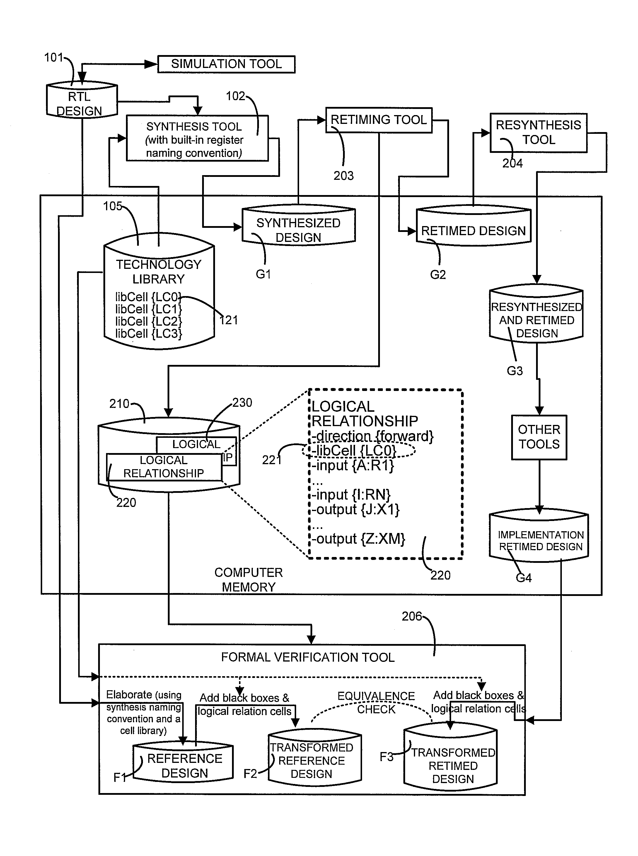
[0049]A ‘netlist’ is a representation of an electronic circuit used to perform optimizations. A netlist consists of cells and nets. A netlist can have a name for identification. The netlist name can also be referred to as the design name. A ‘net’ represents the connection on which electrical signals travel between cells. A ‘cell’ represents an electronic device that performs a certain function. A cell has a name for identification. A ‘library cell’ is a description of the properties of identical cells instantiated in a netlist of an electronic circuit. The description includes the pins of the cells and the pin names as well the functional relationship (i.e. the output pin values as a function of the signal values at the input pins) between the pins, e.g. specified as a method to compute the signal values at the output pins given the signal values at the input pins). Optionally the description may include physical information for the cells such as delay information, area or floorplan...


PUM


Abstract

A memory is encoded with data that represents a reference IC design, a retimed IC design, and logical relationships, wherein at least one logical relationship describes combinational logic without reference to structural information, such as actual cells that have been instantiated in the IC designs. The logical relationships are used to instantiate logic described therein, and to define one or more black boxes as being functionally inverse of the logic. Each instantiated logic and its functionally inverse black box are thereafter added to the reference IC design to obtain a transformed reference IC design. A transformed retimed IC design is also obtained by addition of the instantiated logic(s) and functionally inverse black box(es) to the retimed IC design. These two transformed IC designs are then supplied to an equivalence checker, for formal verification.

Description

CROSS-REFERENCE TO PARENT APPLICATION[0001]This application is a divisional application of U.S. patent application Ser. No. 11 / 495,136 entitled “TRANSFORMATION OF IC DESIGNS FOR FORMAL VERIFICATION” by Muzaffer Hiraoglu and Peter Wilhelm Josef Zepter, filed on Jul. 28, 2006. U.S. patent application Ser. No. 11 / 495,136 is incorporated by reference herein in its entirety, including Appendices A and B therein.BACKGROUND[0002]1. Field of the Invention[0003]The invention relates to verification of a design of an integrated circuit (IC). More specifically, the invention relates to a method and an apparatus for formal verification of an IC design that has been retimed, by moving sequential cells across one or more cells of combinational logic.[0004]2. Related Art[0005]Formal verification is well known in the art. See, for example, U.S. Pat. No. 6,336,206 granted to Lockyear on Jan. 1, 2002 and U.S. Pat. No. 6,668,362 granted to McIlwain et al. on Dec. 23, 2003 both of which are incorporate...

Claims


Application Information

Patent Timeline
Patent Type & Authority Applications(United States)
IPC IPC(8): G06F17/50
CPCG06F17/504G06F30/3323
Inventor HIRAOGLU, MUZAFFERJOSEF ZEPTER, PETER WILHELM
Owner SYNOPSYS INC
Why Eureka
Try Eureka