
Artwork drying cabinet and method

Inactive Publication Date: 2009-12-03
JONAITIS HELBERT J +1
View PDF5 Cites 13 Cited by
  • Summary
  • Abstract
  • Description
  • Claims
  • Application Information

AI Technical Summary

Benefits of technology

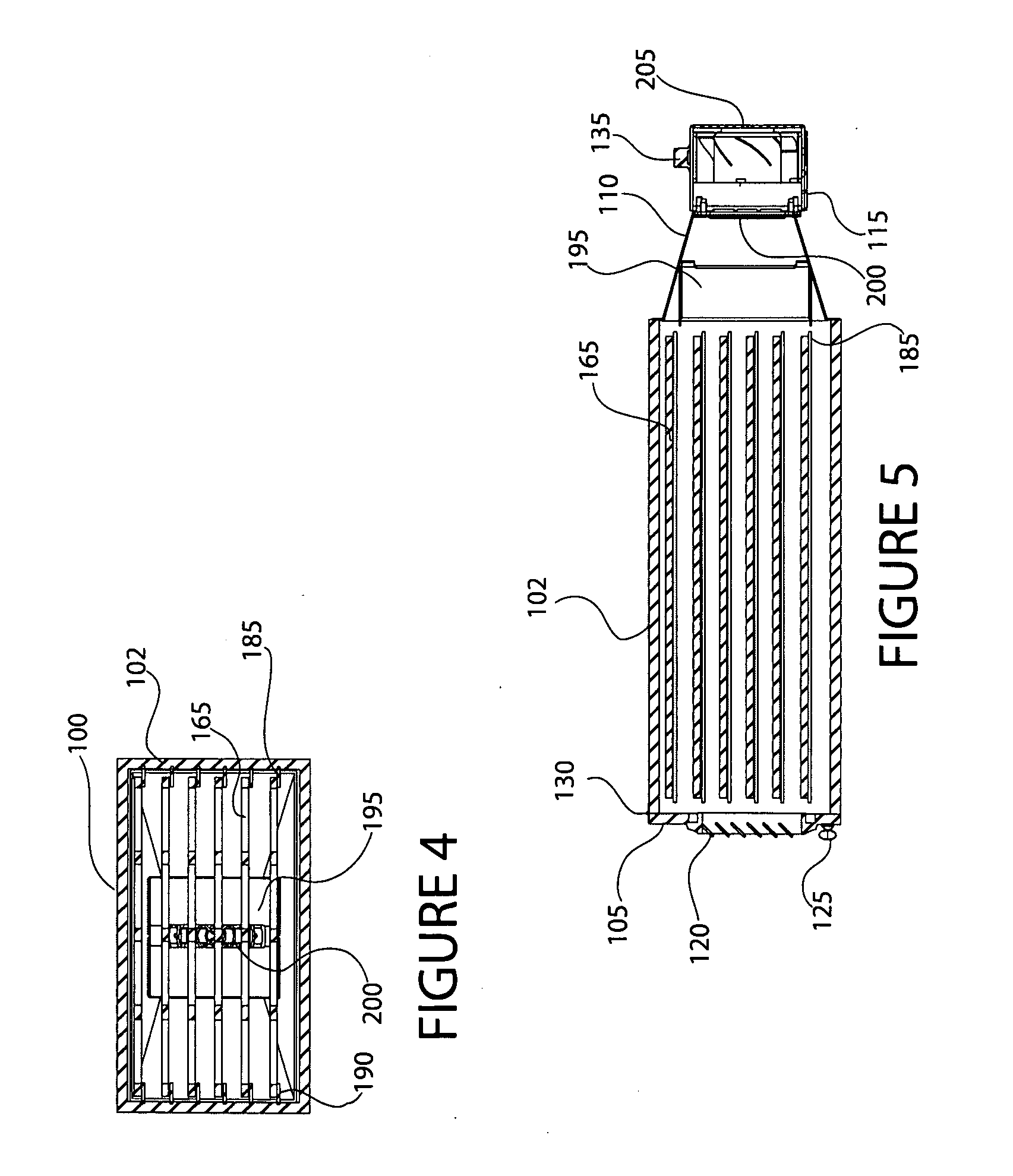
[0010]The diffuser evenly distributes parallel laminar streams of heated air above and below each shelf. The shelves comprise removable supportive frameworks featuring relatively large openings. Streams of heated air contact the top and, through the openings, the bottom of the artwork supported on the shelf. The dual sided contact maintains an even pressure distribution and facilitates drying.

Problems solved by technology

First and foremost, hair dryers are highly inefficient, consuming about 2000 watts or more to rapidly heat a nichrome wire heating element. Several artisans drying their artworks, each using a hair dryer in the same room, may easily overload a circuit and trip a circuit breaker. Tripped circuit breakers and blown fuses are frequent occurrences in art classes. Additionally, because much of the heated air is deflected from the surface of the artwork, the temperature of the room is increased. In a small room with several artists using hair dryers, the temperature can quickly increase to an uncomfortable level.
Furthermore, anyone who has dried their hair with a blow dryer will attest to annoying noise levels.
The noise in a room with several hair dryers activated at the same time is deafening, drowning out all other sounds, including telephones and speech.
Moreover, hair dryers tend to damage artwork.
Even if a hair dryer is positioned a safe distance to avoid physical deformation, unless it is continuously moved, the heat transfer will steadily increase the temperature of the targeted artwork until an unsafe temperature is reached, causing damage.
Such damage may include warping, discoloration, and cracking.

Method used


Image

  • Artwork drying cabinet and method
  • Artwork drying cabinet and method
  • Artwork drying cabinet and method

Examples


Embodiment Construction

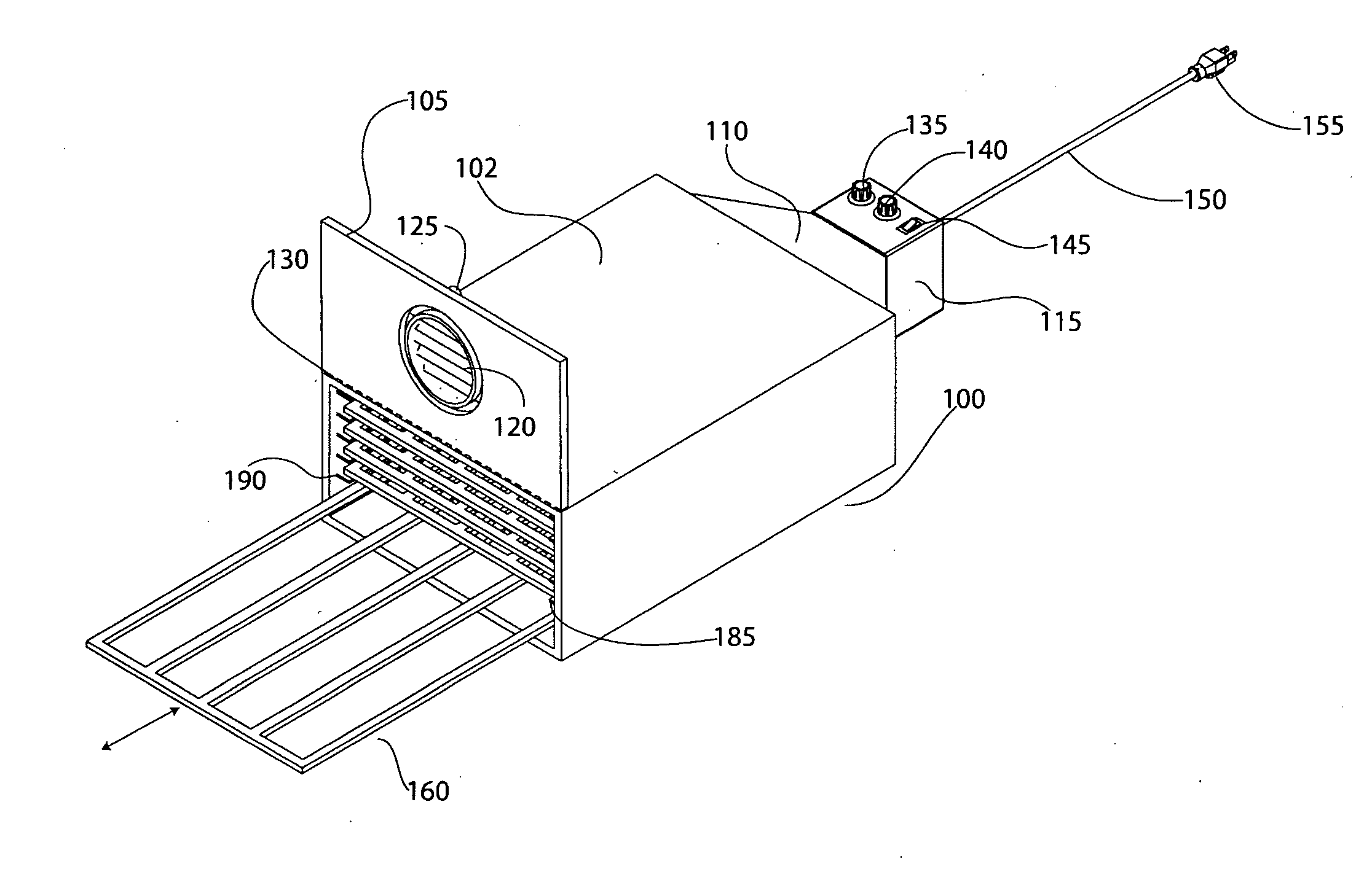
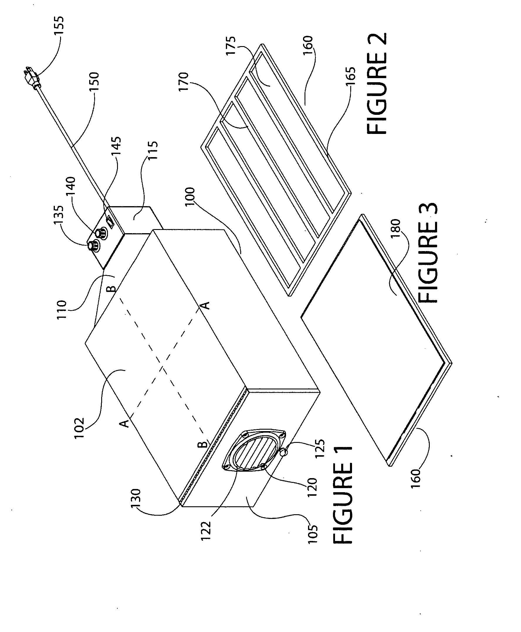
[0031]Referring to the Figures, in which like parts are indicated with the same reference numerals, various views of an exemplary artwork drying cabinet and components thereof according to principles of the invention are shown. With particular reference to FIGS. 1, 6 and 7, perspective views of an exemplary artwork drying cabinet 100 according to principles of the invention are shown. The cabinet 100 includes a housing 102 that defines an interior compartment. The exemplary housing 102 comprises parallel top and bottom panels and parallel side panels. As discussed below, the housing 102 contains removable shelves for supporting artwork to be dried. A current of heated air flows over the shelves in the housing 102.

[0032]A door 105 is provided to enable access to the interior compartment of the housing. A handle 125 facilitates manually opening and closing the door 105. The exemplary door 105 is mounted with door hardware, such as a hinge 130 attached to the housing 102. Optionally, a...


PUM


Abstract

An artwork drying cabinet includes a housing that defines an interior drying compartment. A plurality of removable shelves are provided in parallel spaced relation within the compartment. A hinged door provides access to the compartment for purposes of loading and removing shelves with artwork. The door includes a vent to exhaust moisture laden air from the compartment. A blower and heating element are provided to supply a heated current of air to the compartment. A shroud couples the blower and heating element to the cabinet and directs the flow of heated air into the cabinet. The blower sends the current of air over the heating element through a diffuser comprising a v-shaped baffle with a central elongated opening along the vertex. Controls are provided to regulate air speed and temperature. An optional timer controls the duration of a drying cycle. The diffuser evenly distributes parallel laminar streams of heated air above and below each shelf. The shelves feature relatively large openings that allow streams of heated air to simultaneously contact the top and the bottom of the artwork supported on the shelf. The dual sided contact maintains an even pressure distribution and facilitates drying.

Description

RELATED APPLICATION[0001]This application is a Nonprovisional of and claims the benefit of priority of U.S. Provisional Application 61 / 056,581 filed 28 May 2008, the entire contents of which are incorporated herein by this reference and made a part hereof.FIELD OF THE INVENTION[0002]This invention relates generally to drying artwork, and, more particularly, to a system and method for efficiently accelerating the drying of a plurality of wet artwork pieces.BACKGROUND[0003]Artisans have long used hair dryers to accelerate the drying of paintings and other wet artwork. Such artwork may include a painting, faux painting sample, a finished cabinet or door, or the like. A continuously moving hair dryer aimed at a wet substance will substantially reduce the amount of time required to dry by increasing the rate of evaporation of liquid components. Unfortunately, however, hair dryers have serious shortcomings.[0004]First and foremost, hair dryers are highly inefficient, consuming about 2000 ...

Claims


Application Information

Patent Timeline
IPC IPC(8): F26B3/02F26B25/06F26B25/18F26B21/06
CPCF26B9/066F26B21/12F26B21/10F26B21/004
Inventor JONAITIS, HELBERT J.WALLIS, STEVEN
Owner JONAITIS HELBERT J
Learn More