Drying apparatus for pet

Inactive Publication Date: 2010-12-09
ETIRA
5 Cites 24 Cited by

AI-Extracted Technical Summary

Problems solved by technology

Currently, a lot of households keep pets such as dogs and cats, and while pets are sources of pleasure for people, they can also become sources of diseases and odors if hygienic care—especially regular baths—are not administered.
Furthermore, fur, foreign substances, etc. from pets become contaminants of surrounding environments.
Here, if a pet (whose entire body is covered with fur) is not properly and expediently dried following a bath, the pet is made susceptible to skin diseases because its skin is much weaker than a person's, or the pet may begin to smell.
First, due to weight considerations, a typical hair dryer that is used hand-held employs a small motor that rotates at high speed to blow air, thus generating ultra-high frequency sound inaudible to humans, but highly audible and disconcerting for pets.
Second, the temperature at the outlet of a hair dryer used by humans is high at approximately 55° C. However, because the skin of a pet that is covered with fur is frail, when hot air of a high te...

Method used

[0043]The main body case 10 defines a rectangular outlet 14 that projects at one side. A heating member 12 is installed in the inside of the outlet 14. Here, an outlet grill 13 for preventing impurities of a predetermined size from entering may be installed between the outlet 14 and the heating member 12. Also, an outlet cover 16 is hinged to the opening of the outlet 14 to prevent entry of finer impurities such as dust into the outlet 14 during storage, and a torsion spring may be provided at the hinge connecting portion to automatically open the outlet cover 16. Moreover, a handle 15 may be installed on the outside of the main body case 10 to facilitate grasping. Further, in order to allow air to be easily suctioned, a plurality of inlets 17 may be defined over a predetermined area. A filter for preventing suctioning of impurities may be detachably mounted on the inlets 17.
[0044]The cross-flow fan 20 is installed in a length direction within the main body case 10. That is, the cross-flow fan 20 functions to discharge air over a predetermined width in a longitudinal direction of the cross-flow fan 20. A shaft at one end of the cross-flow fan 20 is rotatably coupled to the main body case 10, with a bearing (not provided with a reference number in the diagrams) interposed therebetween. A shaft at the other end of the cross-flow fan 20 is connected to a fan motor 22, so that the cross-flow fan 20 is rotated by the driving force of the fan motor 22. The fan motor 22 may be connected to a stepless transmission controller. Thus, a user may finely control the rotating speed of the cross-flow fan 20. Here, the stepless transmission controller may be configured with a typical stepless transmission controlling circuit formed between a controller and the fan motor 22. That is, the rpm of the cross-flow fan 20 can be steplessly controlled by varying the rotation of the fan motor 22 according to a variable resistance value input by a user. As another means, a digitally controlling device may be employed that can finely adjust the rpm through a program whenever an up or down button is pressed to input signals to a control micom. Accordingly, the strength of blown air can be controlled to be suitable for the temperament of a particular pet. By employing a cross-flow fan 20 in the drying apparatus of the present invention, air can be blown at a uniform intensity through an outlet 14 having a predetermined length (longitudinal length). Therefore, by uniformly blowing air during drying along the entire body of a pet, drying efficiency can be increased to enable speedy drying.
[0051]Here, as a method for performing pivoting with the swing motor 40, electrical signals for reciprocal forward/reverse rotation may be applied to a low-speed motor that rotates at low speed (preferably between 4 to 6 rpm), or reciprocal rotation may be achieved within a set range by means of a driving cam or gear assembly. The main body case 10 may be pivoted over a set angular range through a thus-driven swing motor 40 to allow a user to use both hands to dry a pet, thereby facilitating drying and reducing drying time. In other words, in order to blow air over a wide area, the present invention pivots the main body case 10 with the swing motor 40 to automatically control the angular range in which air is discharged.
[0052]This is distinctly different in terms of configuration and function from a blown air direction controlling method employed in a typical indoor cooling/heating apparatus. Specifically, a blown air direction controlling method employed in a related art cooling/heating apparatus has a damper grill (or blade) installed at the outlet, whereupon the damper grill is moved upward and downward, so that discharged air collides with the damper grill and is directionally controlled. However, this method involves the drawbacks of reducing discharged pressure and generating noise. Conversely, the blown air direction controlling method of the present invention automatically controls the blown air discharging direction by pivoting the main body case 10 itself within a predetermined angular range with the swing motor 40, so that reduction of discharged pressure of the blown air can be prevented and noise generation can also be prevented. The ability of the present invention to be manufactured in a configuration that employs the swing motor 40 to control the direction of blown air is attributable to its ability to be manufactured in a size smaller than a typical cooling/heating apparatus because of its designation of use for small-sized pets.
[0055]Referring to FIG. 4, the second embodiment of the present invention may be configured with a fan motor 22 disposed inside a main body case 10. Through this configuration, the exterior of the apparatus can be manufactured in a simpler shape.
[0058]That is, the manual knob 70 enables a user to fix the direction of the outlet 14 at a desired angle for use. Accordingly, the cost of the product can be lowered through simplifying the product, and not only the body of a pet, but the pet's feet and extremities can be intensively dried.
[0060]Moreover, because the present invention may be used in a floor-standing state, it can use a mi...

Benefits of technology

[0022]First, by using the benefits of a rotating fan that can discharge air over an extended width to uniformly discharging air over the entire body of a pet (approximately 30-40 cm wide in the case of a typical lapdog), the present invention can achieve the effects of expediting drying while at the same time reducing fatigue from a prolonged drying process to a person and a pet, and also obviating a pet contracting a respiratory ailment.
[0023]Second, the present invention may be used in a floor-standing configuration, allowing a user to use both hands to dry a pet, thus facilitating drying.
[0024]Third, instead of using a typical ±5-watt miniature motor (that is rotated at a high speed of 10,000...

Abstract

The present invention provides a cross-flow type drying apparatus for a pet, that is capable of quickly performing drying by blowing air uniformly on the entire body of a pet and simultaneously facilitating drying by reducing the amount of stress that a pet is subjected to. The cross-flow type drying apparatus includes: a main body case defining an outlet and an inlet and including a heating member installed within; a cross-flow fan installed in a longitudinal direction within the main body case to rotate; and a stand coupled to enable the main body case to pivot to a predetermined angle. This configuration can reduce drying time and easily perform drying the pet, and can lower manufacturing cost to reduce the financial burden placed on a user.

Application Domain

Grooming devicesDrying machines

Technology Topic

EngineeringManufacturing cost reduction +2

Image

  • Drying apparatus for pet
  • Drying apparatus for pet
  • Drying apparatus for pet

Examples

  • Experimental program(4)

Example

First Embodiment
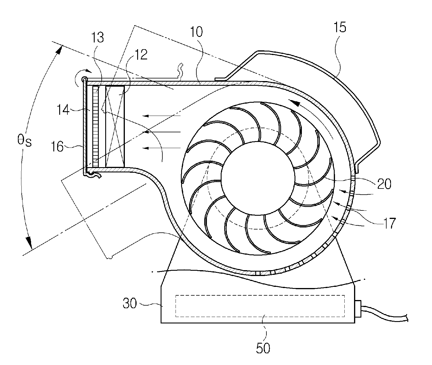
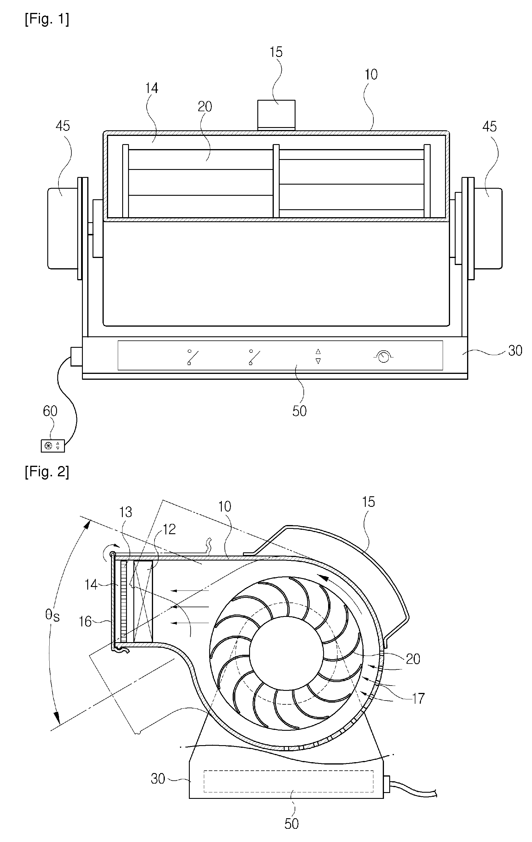
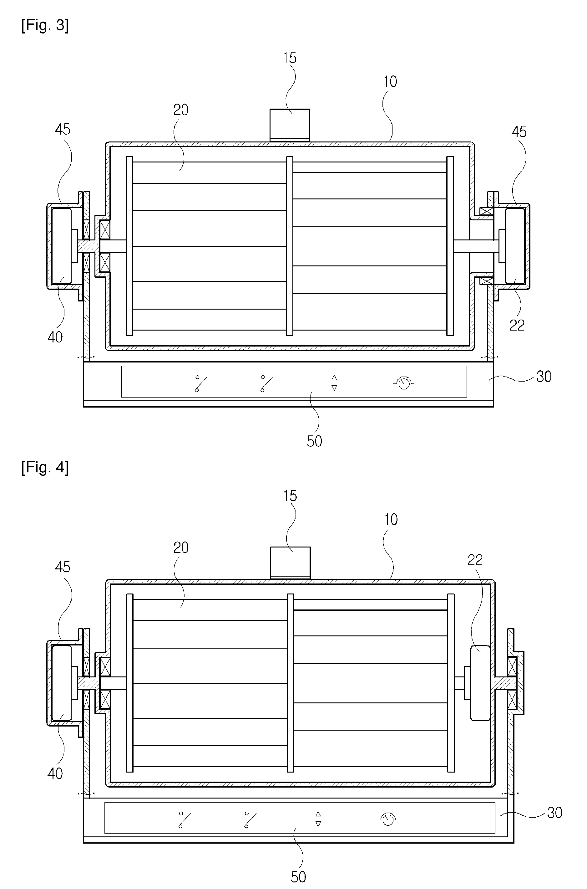
[0041]FIG. 1 is a frontal view illustrating the structure of a cross-flow drying apparatus for a pet according to a first embodiment of the present invention, FIG. 2 is a state diagram schematically illustrating the operation of a cross-flow drying apparatus for a pet according to the first embodiment of the present invention, and FIG. 3 is a schematic view illustrating the structure of a cross-flow drying apparatus for a pet according to the first embodiment of the present invention.
[0042]As illustrated, a drying apparatus for a pet according to the present invention includes a main body case 10, a cross-flow fan 20, and a stand 30.
[0043]The main body case 10 defines a rectangular outlet 14 that projects at one side. A heating member 12 is installed in the inside of the outlet 14. Here, an outlet grill 13 for preventing impurities of a predetermined size from entering may be installed between the outlet 14 and the heating member 12. Also, an outlet cover 16 is hinged to the opening of the outlet 14 to prevent entry of finer impurities such as dust into the outlet 14 during storage, and a torsion spring may be provided at the hinge connecting portion to automatically open the outlet cover 16. Moreover, a handle 15 may be installed on the outside of the main body case 10 to facilitate grasping. Further, in order to allow air to be easily suctioned, a plurality of inlets 17 may be defined over a predetermined area. A filter for preventing suctioning of impurities may be detachably mounted on the inlets 17.
[0044]The cross-flow fan 20 is installed in a length direction within the main body case 10. That is, the cross-flow fan 20 functions to discharge air over a predetermined width in a longitudinal direction of the cross-flow fan 20. A shaft at one end of the cross-flow fan 20 is rotatably coupled to the main body case 10, with a bearing (not provided with a reference number in the diagrams) interposed therebetween. A shaft at the other end of the cross-flow fan 20 is connected to a fan motor 22, so that the cross-flow fan 20 is rotated by the driving force of the fan motor 22. The fan motor 22 may be connected to a stepless transmission controller. Thus, a user may finely control the rotating speed of the cross-flow fan 20. Here, the stepless transmission controller may be configured with a typical stepless transmission controlling circuit formed between a controller and the fan motor 22. That is, the rpm of the cross-flow fan 20 can be steplessly controlled by varying the rotation of the fan motor 22 according to a variable resistance value input by a user. As another means, a digitally controlling device may be employed that can finely adjust the rpm through a program whenever an up or down button is pressed to input signals to a control micom. Accordingly, the strength of blown air can be controlled to be suitable for the temperament of a particular pet. By employing a cross-flow fan 20 in the drying apparatus of the present invention, air can be blown at a uniform intensity through an outlet 14 having a predetermined length (longitudinal length). Therefore, by uniformly blowing air during drying along the entire body of a pet, drying efficiency can be increased to enable speedy drying.
[0045]One end of the main body case 10 is rotatably coupled to a stand 30 with a bearing (not assigned a reference number in the diagrams) in between. A swing motor 40 fixed to the stand 30 is coupled to the other end of the main body case 10 to pivot the main body case 10 to a predetermined angle. Here, a motor cover 45 may be installed on the swing motor 40 and the fan motor 22. A controller 50 for controlling the swing motor 40 and the fan motor 22 is installed on the lower portion of the stand 30.
[0046]Here, a remote controller 60 (in FIG. 1) may be installed on the controller 50 to enable a user to freely control the apparatus from a remote distance. Here, the remote controller 60 may be a typical wired or wireless controller.
[0047]The cross-flow drying apparatus for a pet according to the first embodiment of the present invention will be described below in terms of its functions and effects.
[0048]First, when power is supplied to the drying apparatus of the present invention, the cross-flow fan 20 is driven inside the main body case 10. Accordingly, a natural breeze or a heated breeze is discharged through the outlet 14 according to a manipulation of the controller 50. The swing motor 40 reciprocally pivots only the main body case 10 (which encloses the cross-flow fan 20 fixed to and rotated by the fan motor 22, and has the inlets 17 and outlet 14) by a predetermined angular range.
[0049]In detail, as illustrated in FIG. 2, the pivoting angle (θs) of the main body case 10 is a predetermined angular range over which hot air is reciprocally pivoted and discharged onto the entire body of a pet. Of course, a user is able to fix the main body case 10 at a suitable angle for use as desired.
[0050]Thus, because an angle for discharging hot air can be set within a predetermined range or discharging may be performed through automatic pivoting, a user can hold a pet with one hand while using a tool such as a brush with the other hand to arrange hairs (fur) of the pet.
[0051]Here, as a method for performing pivoting with the swing motor 40, electrical signals for reciprocal forward/reverse rotation may be applied to a low-speed motor that rotates at low speed (preferably between 4 to 6 rpm), or reciprocal rotation may be achieved within a set range by means of a driving cam or gear assembly. The main body case 10 may be pivoted over a set angular range through a thus-driven swing motor 40 to allow a user to use both hands to dry a pet, thereby facilitating drying and reducing drying time. In other words, in order to blow air over a wide area, the present invention pivots the main body case 10 with the swing motor 40 to automatically control the angular range in which air is discharged.
[0052]This is distinctly different in terms of configuration and function from a blown air direction controlling method employed in a typical indoor cooling/heating apparatus. Specifically, a blown air direction controlling method employed in a related art cooling/heating apparatus has a damper grill (or blade) installed at the outlet, whereupon the damper grill is moved upward and downward, so that discharged air collides with the damper grill and is directionally controlled. However, this method involves the drawbacks of reducing discharged pressure and generating noise. Conversely, the blown air direction controlling method of the present invention automatically controls the blown air discharging direction by pivoting the main body case 10 itself within a predetermined angular range with the swing motor 40, so that reduction of discharged pressure of the blown air can be prevented and noise generation can also be prevented. The ability of the present invention to be manufactured in a configuration that employs the swing motor 40 to control the direction of blown air is attributable to its ability to be manufactured in a size smaller than a typical cooling/heating apparatus because of its designation of use for small-sized pets.
[0053]Other embodiments of the present invention will be described below with reference to the drawings.
[0054]FIG. 4 is a schematic view illustrating the structure of a cross-flow drying apparatus for a pet according to a second embodiment of the present invention, FIG. 5 is a schematic view illustrating the structure of a cross-flow drying apparatus for a pet according to a third embodiment of the present invention, and FIG. 6 is an enlarged view of a portion A-A in FIG. 5.

Example

[0055]Referring to FIG. 4, the second embodiment of the present invention may be configured with a fan motor 22 disposed inside a main body case 10. Through this configuration, the exterior of the apparatus can be manufactured in a simpler shape.

Example

[0056]Referring to FIGS. 5 and 6, in the third embodiment of the present invention, instead of the swing motor 40 used in the above-described first embodiment to pivot the main body case 10, a manual knob 70 may be installed. While not illustrated in the drawings, the fan motor 22 may be disposed within the main body case 10 as in the second embodiment.
[0057]The manual knob 70 may be formed in a size that can be easily grasped by a user, and may be fixed at one end of the main body case 10. In detail, as illustrated in FIG. 6, a tension ball 72 is installed within a side of the manual knob 70 to be elastically supported by a spring 74 with a portion thereof exposed, and a plurality of latching recesses 32 are formed at predetermined intervals in a side surface of the stand 30 such that the tension ball 72 faces and can be seated therein. To dry a pet with this configuration, when a user rotates the manual knob 70 in a desired direction to set the discharging angle, the tension ball 72 is seated in a latching recess 32 to fix the direction of the outlet at a predetermined angle.
[0058]That is, the manual knob 70 enables a user to fix the direction of the outlet 14 at a desired angle for use. Accordingly, the cost of the product can be lowered through simplifying the product, and not only the body of a pet, but the pet's feet and extremities can be intensively dried.
[0059]Of course, a height adjusting member capable of adjusting vertical height may be provided on the stand 30 to adjust the height of the apparatus (or, the height of the outlet) according to the size of a pet. That is, foldable legs are installed on the floor of the stand 30 to enable height adjustment when required, according to the size of a pet, by folding or extending the foldable legs.
[0060]Moreover, because the present invention may be used in a floor-standing state, it can use a mid to large-sized motor with substantially low operating noise. However, the generation of operating noise from even such motors cannot be prevented at the source. Therefore, a separate melody emitting device may be built into the controller 50 for pets that are especially sensitive to such operating noise. The melody emitting device is a well-known device used widely for playback of music or musical therapy. Therefore, the apparatus may be configured to minimize stress from operating noise during drying by playing back relaxing music such as sounds of nature.

PUM

no PUM

Description & Claims & Application Information

We can also present the details of the Description, Claims and Application information to help users get a comprehensive understanding of the technical details of the patent, such as background art, summary of invention, brief description of drawings, description of embodiments, and other original content. On the other hand, users can also determine the specific scope of protection of the technology through the list of claims; as well as understand the changes in the life cycle of the technology with the presentation of the patent timeline. Login to view more.

Similar technology patents

Overtaking assisting method and system for vehicle

ActiveCN107097773AReduce fatigueReduce potential riskExternal condition input parametersPotential riskDriver safety
Owner:GEELY AUTOMOBILE INST NINGBO CO LTD +1

Horizontal type cervical vertebra traction bed adaptive to physiological curvature of cervical vertebrae

ActiveCN104083240AGood for treatment purposesReduce fatigueChiropractic devicesFractureVertebraDisease
Owner:THE AFFILIATED HOSPITAL TO CHANGCHUN UNIV OF CHINESE MEDICINE

Classification and recommendation of technical efficacy words

  • Reduce fatigue
  • Facilitate drying

Dictation selection

ActiveUS8032372B1Reduce fatigueReduce physical stressNatural language translationComputer-assisted medical data acquisitionMedical transcriptionFeature set
Owner:DELIVERHEALTH SOLUTIONS LLC

Locking hinge connector apparatus

InactiveUS20060016047A1Reduce back strainReduce fatigueBrush bodiesHingesHinge angleEngineering
Owner:BLACKMAN GARY PALMER +1

Artwork drying cabinet and method

InactiveUS20090293302A1Facilitate dryingDistribute pressureAgriculture tools and machinesDrying solid materials with heatEngineeringHeating element
Owner:JONAITIS HELBERT J +1

Polymeric composition suitable for manufacturing heat sealable films or sheets

InactiveUS20090082496A1Material degradation be preventFacilitate dryingFibre treatmentConductive materialPolyethylene terephthalate glycolMelting point
Owner:DUPONT IND BIOSCIENCES USA LLC
Why Eureka
Try Eureka