Mobile Ball Hopper and Sport Bag Carrier

a technology of ball hopper and bag carrier, which is applied in the field of sports goods, can solve the problems of not being able to easily adapt the base for bins of varying diameters, not allowing height adjustment, etc., and achieves the effects of convenient assembly and disassembly, convenient adjustment, and convenient stowing of the bin cover

a technology of ball hopper and bag carrier, which is applied in the field of sports goods, can solve the problems of not being able to easily adapt the base for bins of varying diameters, not allowing height adjustment, etc., and achieves the effects of convenient assembly and disassembly, convenient adjustment, and convenient stowing of the bin cover

US20090295108A1Inactive Publication Date: 2009-12-03OKU ALBERT HISAYUKI

Image

  • Mobile Ball Hopper and Sport Bag Carrier
  • Mobile Ball Hopper and Sport Bag Carrier
  • Mobile Ball Hopper and Sport Bag Carrier

Examples


Embodiment Construction

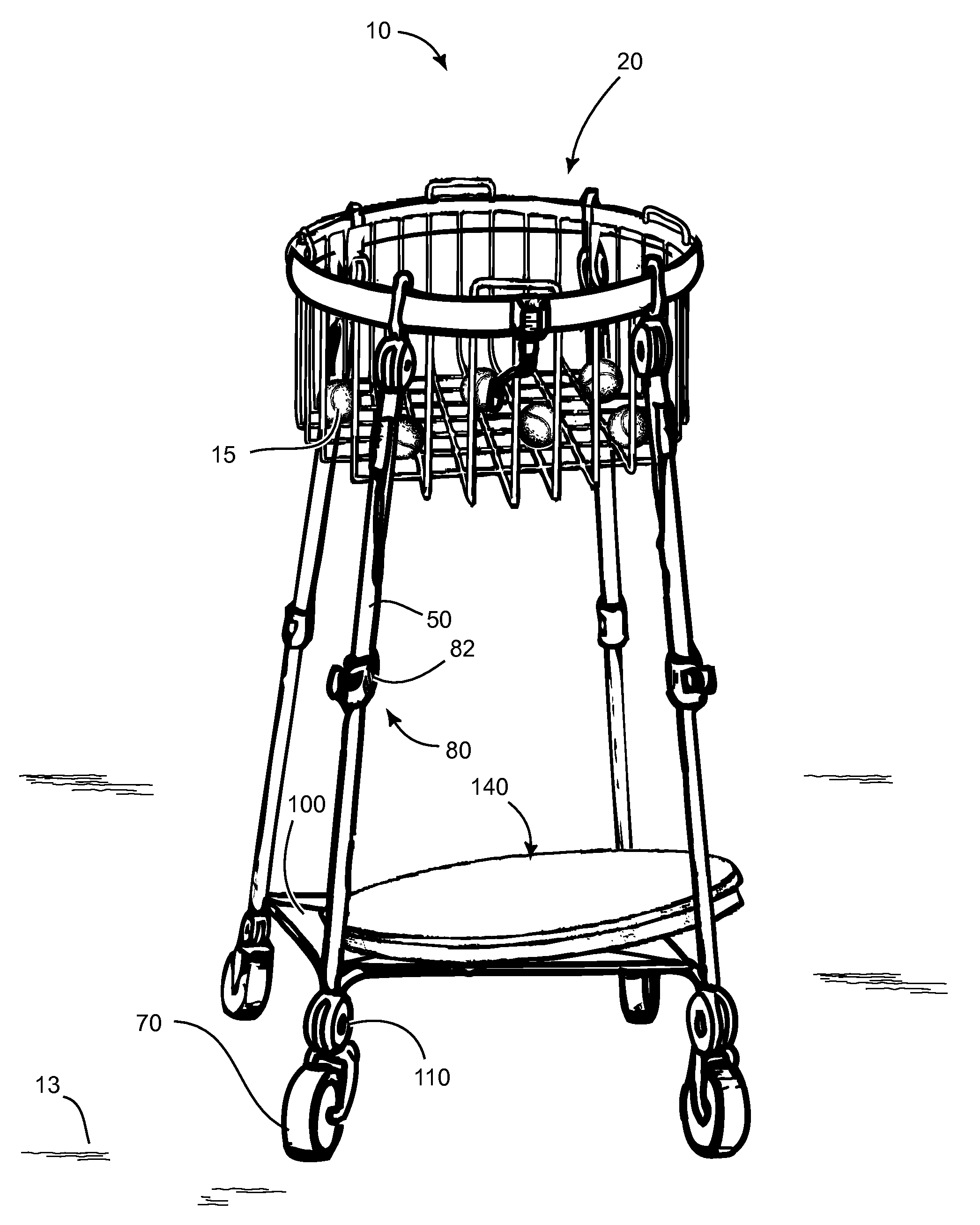
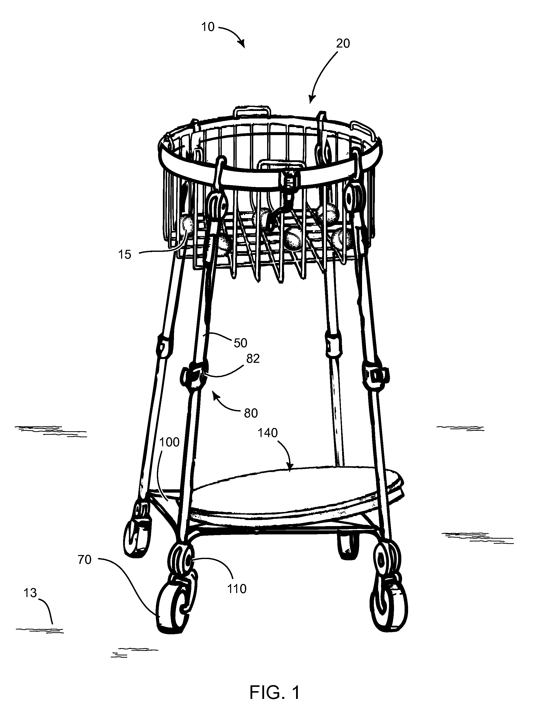
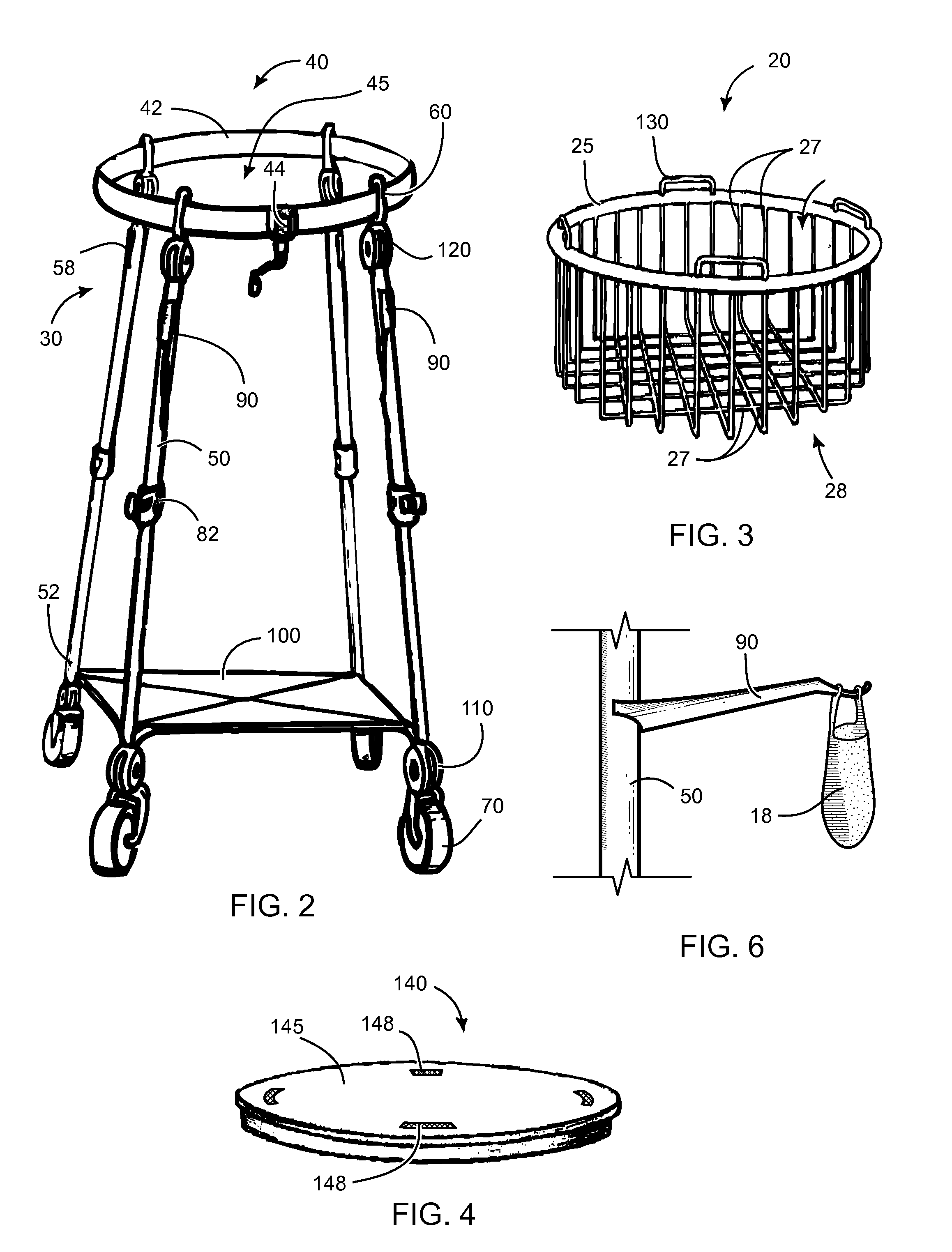
[0017]FIGS. 1 and 2 illustrate a carrier 10 for sporting equipment 15, such as tennis balls, golf balls, or other sporting balls, pucks, birdies, or other equipment. The carrier 10 includes a hopper 20 that has an outer peripheral flange 25 and defines a volume 28 for receiving the sporting equipment therein (FIG. 3). Such a hopper 20 may be formed from a plurality of bent metal wire 27 to form a hopper basket 28, for example. The hopper 20 may also be a molded plastic bucket, a formed sheet metal bucket, a perforated metal bucket, or the like (not illustrated). Preferably the hopper 20 is circular in plan view, although other hopper 20 shapes could be utilized as desired.

[0018]A hopper supporting means 30 comprise an adjustable peripheral support 40 and a plurality of height-adjustable legs 50. Each leg 50 has an upper end 58 fixed to the peripheral support 40 at a band attachment means 60 thereof. Each leg 50 further includes a lower end 52 that terminates at a wheel assembly 70 (...


PUM


Abstract

A carrier for sporting equipment is disclosed that includes a hopper that has an outer peripheral flange and defines a volume for receiving the sporting equipment therein. A hopper supporting means comprise an adjustable peripheral support and a plurality of height-adjustable legs. Each leg has an upper end fixed to the peripheral support at a band attachment means thereof, and a lower end that terminates at a wheel assembly. A lid may be included for covering the hopper and for providing a substantially horizontal surface. Preferably the adjustable peripheral support comprises a resilient band that has an adjustment hand crank attached therealong for adjusting the size of an aperture formed by the band. Each leg is preferably telescoping and further includes a locking means for selectively fixing the height of the leg.

Description

CROSS-REFERENCE TO RELATED APPLICATIONS[0001]Not Applicable.STATEMENT REGARDING FEDERALLY SPONSORED RESEARCH AND DEVELOPMENT[0002]Not Applicable.FIELD OF THE INVENTION[0003]This invention relates to sporting goods, and more particularly to a novel sporting equipment carrier.DISCUSSION OF RELATED ART[0004]Sporting equipment carriers for use on the tennis court or sporting field are well known in the prior art. Such devices typically take the form of a rolling bin or cart into which the sporting equipment may be stowed and transported. Certain drawbacks exist with the prior art, however. For example, users of such devices may have bins for holding the sporting equipment that is of varying sizes, so having a base that is adaptable to varying-sized bins would be advantageous. Devices such as that disclosed in U.S. Pat. No. 6,179,306 to Maxwell on Jan. 30, 2001, teach a rolling base for a bin that is of a fixed size. Further, such a device does not allow for height adjustment, which is d...

Claims


Application Information

Patent Timeline
03 Dec 2009
Publication
US20090295108A1
IPC
B62B3/02
CPC
B62B3/02; B62B3/1496; B62B2206/06; B62B2202/40; B62B5/0013
Inventors
OKU, ALBERT HISAYUKI