Receiving antenna coil

a technology of antenna coil and receiver, which is applied in the direction of antenna details, polarised antenna unit combinations, antennas, etc., can solve the problems of deterioration of antenna characteristics, damage to the insulating film on the surface of the coil, and problems, so as to achieve the effect of reducing the thickness of the coil, balancing and ensuring the volume of the core, and improving the reception characteristi

Active Publication Date: 2009-12-03
SUMIDA CORP
View PDF2 Cites 11 Cited by
  • Summary
  • Abstract
  • Description
  • Claims
  • Application Information

AI Technical Summary

Benefits of technology

[0026]In the receiving antenna coil of the present invention, by making an X-axis winding core part or a Y-axis winding core part of a plurality of bars in a limited region surrounded by a Z-axis receiving coil, the length of the winding core part and the volume of the core are balanced and largely assured, so that the reception characteristic improves. Since a coil is wound around each of the X-axis winding core part and the Y-axis winding core part, the X-axis receiving coil and the Y-axis receiving coil are not wound so as to overlap each other. Therefore, the thickness of the coil can be reduced, and a problem of damage on the coil does not occur. Thus, both improvement in the reception characteristic and miniaturization of the receiving antenna coil are realized.

Problems solved by technology

However, when coils are wound so as to overlap in the crossing direction, tension at the time of winding is concentratedly applied between coil wires, and there is the possibility that an insulating film on the surface of the coil is damaged.
When the insulating film is damaged and the core wire of the coil wire is exposed, short-circuit of the coil occurs, the antenna characteristic deteriorates, and it becomes a problem.
In the case of the cross-shaped core described in WO 2007 / 116797, it is difficult to wind a wire at the intersecting part of the cross, so that it is difficult to assure the sufficient number of turns of the coil.
Since it is generally difficult to assure large volume of a cross-shaped core in a region in a Z-axis receiving coil disposed so as to surround X-axis and Y-axis receiving coils, it is difficult to sufficiently increase the reception characteristic of the X-axis and Y-axis receiving coils.

Method used


Image

  • Receiving antenna coil
  • Receiving antenna coil
  • Receiving antenna coil

Examples


first embodiment

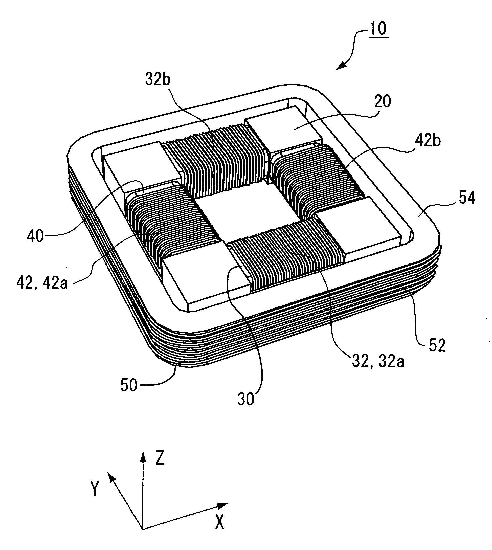
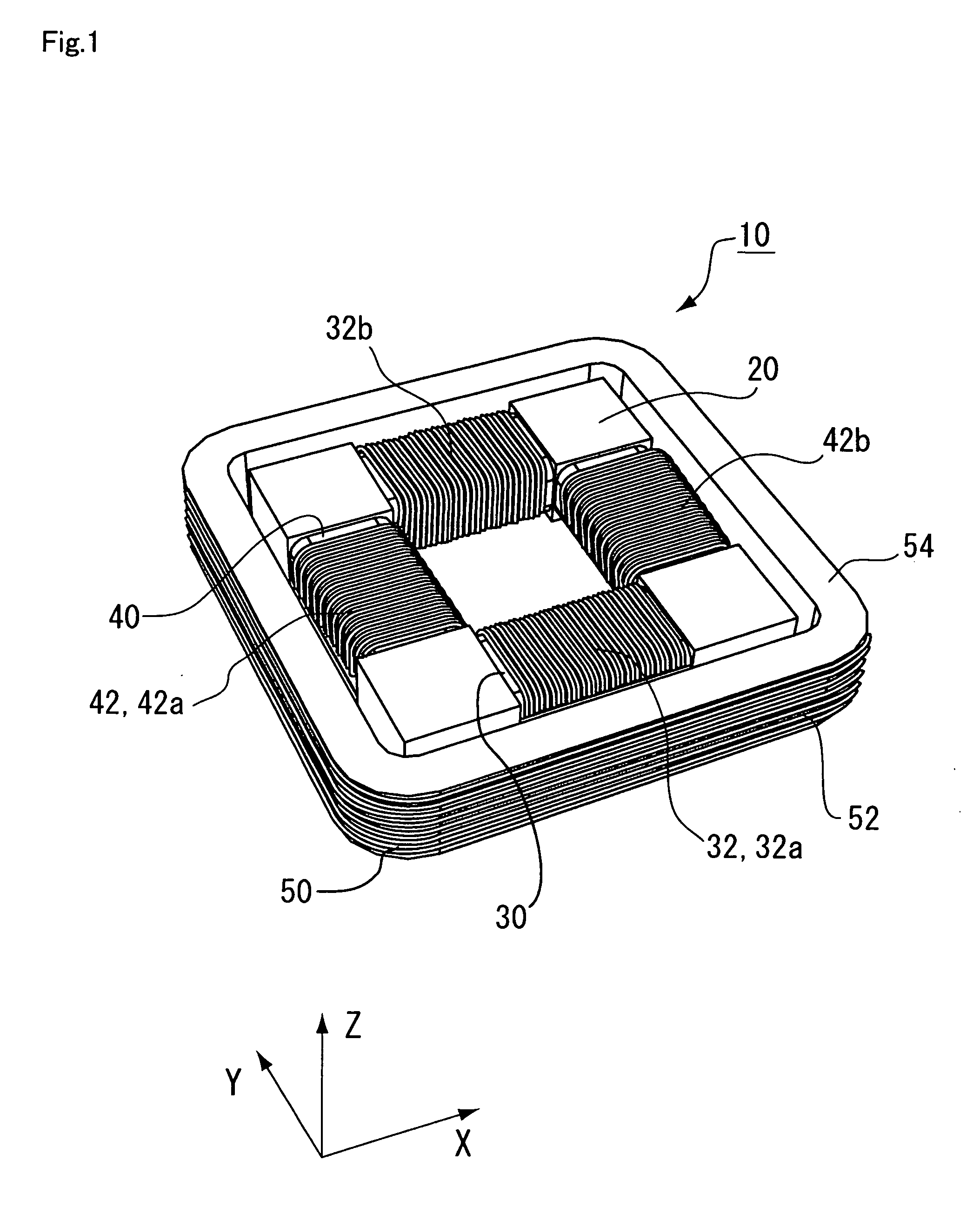
[0041]FIG. 1 is a perspective view showing an example of a receiving antenna coil 10 according to a first embodiment of the present invention.

[0042]First, outline of the receiving antenna coil 10 of the embodiment will be described.

[0043]The receiving antenna coil 10 of the embodiment includes: a core 20 having an X-axis winding core part 30 extending in the X-axis direction and a Y-axis winding core part 40 extending in the Y-axis direction that crosses the X-axis direction; an X-axis receiving coil 32 wound around the X-axis winding core part 30; a Y-axis receiving coil 42 wound around the Y-axis winding core part 40; and a Z-axis receiving coil 52 wound in the Z-axis direction crossing both the X-axis direction and the Y-axis direction so as to surround the X-axis winding core part 30 and the Y-axis winding core part 40.

[0044]The X-axis winding core part 30 and the Y-axis winding core part 40 each made of a magnetic material are provided in the same plane, and at least one of the...

second embodiment

[0085]FIG. 5 is a perspective view showing an example of the core 20 in the receiving antenna coil 10 in the embodiment.

[0086]The core 20 of the embodiment has an H-letter shape in the XY plane. Concretely, a plurality of (two) bars of X-axis winding core parts 30 (X-axis winding core parts 30a and 30b) extending in the X-axis direction are formed in parallel. Intermediate parts in the longitudinal direction of the X-axis winding core parts 30 are connected to each other via a single bar of Y-axis winding core part 40 extending in the Y-axis direction.

[0087]The X-axis winding core part 30a has winding core parts (X-axis winding core parts 30a1 and 30a2) in two places partitioned by a block 22a. The X-axis winding core parts 30a1 and 30a2 are provided apart from each other on the same axis. The Y-axis winding core part 30b has a similar configuration. Core winding parts (X-axis winding core parts 30b1 and 30b2) in two places are provided apart from each other on the same axis by a bl...

third embodiment

[0109]FIG. 9 is a perspective view showing an example of the core of the embodiment.

[0110]The core 20 of the embodiment is constructed by combining an X-axis core 34 including the X-axis winding core part 30 and a Y-axis core 44 including the Y-axis winding core part 40. The embodiment is different from the first embodiment with respect to the point that at least one of the X-axis core 34 and the Y-axis core 44 has an engagement part 62 for making the X-axis core 34 and the Y-axis core 44 engage with each other.

[0111]The X-axis core 34 may be made of a single member having a plurality of bars of X-axis winding core parts 30 or may be constructed by combining a plurality of members each having a single bar of X-axis winding core part 30. The Y-axis core 44 has a similar configuration.

[0112]The core 20 of the embodiment is constructed by combining the plurality of X-axis cores 34 or Y-axis cores 44. The X-axis core 34 has a single bar of X-axis winding core part 30, and the Y-axis cor...


PUM


Abstract

The present invention provides a receiving antenna coil capable of realizing both improvement in the reception characteristic and miniaturization. In a receiving antenna coil, at least one of an X-axis winding core part and a Y-axis winding core part is formed in a plurality of bars. While increasing occupancy of the winding core parts (the X-axis winding core part and the Y-axis winding core part) in a region in the XY plane surrounded by a Z-axis receiving coil, the length of the winding core parts can be assured long. Further, since the X-axis winding core part and the Y-axis winding core part are provided in the same plane, the height of the core is suppressed, and the dimension of the entire receiving antenna coil can be suppressed.

Description

[0001]This application is based on Japanese patent application No. 2008-145465, the content of which is incorporated hereinto by reference.BACKGROUND[0002]1. Technical Field[0003]The present invention relates to a receiving antenna coil in which coils are wound in X-axis, Y-axis, and Z-axis directions which cross one another.[0004]2. Related Art[0005]A receiving antenna coil is used, as an example, by being mounted on a remote controller for locking / unlocking a keyless entry system in a car or a house. To make transmission / reception of information between a control unit on a car or house side and the controller more reliable, in recent years, improvement in a reception characteristic of the receiving antenna coil is demanded. On the other hand, to improve portability for the user, a request for miniaturization of the receiving antenna coil is also increasing.[0006]Techniques of this kind disclosed in, for example, Japanese Unexamined Patent Publication No. 2003-92509 and WO 2007 / 116...

Claims


Application Information

Patent Timeline
Patent Type & Authority Applications(United States)
IPC IPC(8): H01Q7/08
CPCH01Q1/3241H01Q21/24H01Q7/08
Inventor SATO, TSUYOSHI
Owner SUMIDA CORP
Why Eureka
Try Eureka