Image forming apparatus and control method thereof

a technology of image forming apparatus and control method, which is applied in the direction of digital output to print units, instruments, digital computers, etc., can solve the problems of affecting usability, affecting the accuracy of image forming, so as to reduce the amount of toner used, shorten the time taken for circumference detection, and improve the accuracy of density

Active Publication Date: 2009-12-03
CANON KK
View PDF21 Cites 22 Cited by
  • Summary
  • Abstract
  • Description
  • Claims
  • Application Information

AI Technical Summary

Benefits of technology

[0015]The present invention enables realization of an image forming apparatus which shortens the time taken for circumference detection, reduces the amount of toner used, and measures the circumference or detects an accurate density.

Problems solved by technology

If the circumference is used as a fixed value, an error occurs in specifying a position.
However, the conventional techniques suffer the following problems.
A long circumference measurement time prolongs the period (so-called downtime) during which no image can be formed, impairing usability.
Even if usability can be maintained, the cost rises owing to an optical detection mark and optical sensor for measuring the circumference of an intermediate transfer member, as described above.
In some cases, cleaning may take a long time.

Method used


Image

  • Image forming apparatus and control method thereof
  • Image forming apparatus and control method thereof
  • Image forming apparatus and control method thereof

Examples


first embodiment

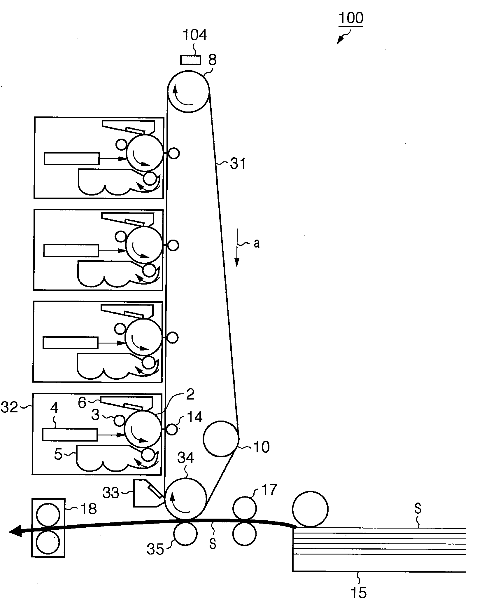
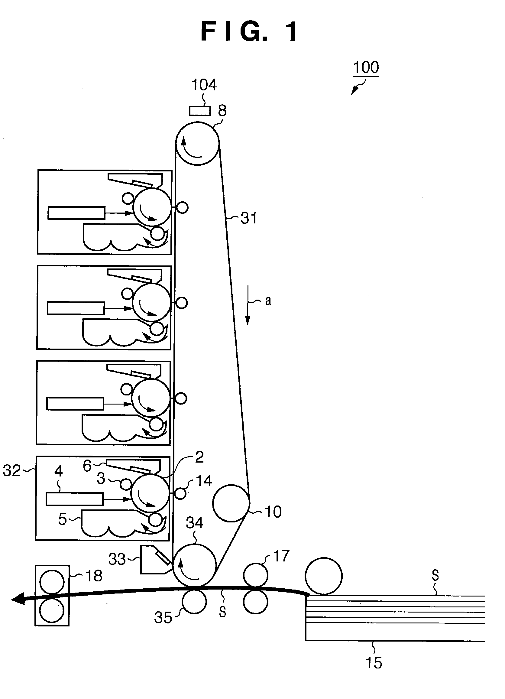
[0045]The first embodiment will be explained with reference to FIGS. 1 to 15. In the first embodiment, the present invention is applied to a color image forming apparatus. The present invention is also applicable to a monochrome image forming apparatus. The image forming apparatus is, for example, a printer, copying machine, multi-functional peripheral, or facsimile apparatus. The first embodiment will exemplify an intermediate transfer method. The intermediate transfer method forms a toner image on a drum-like image carrier, preliminarily transfers the toner image to an intermediate transfer member (intermediate transfer belt), and secondarily transfers the toner image from the intermediate transfer member to a printing material. The printing material is also called, for example, a transfer material, printing medium, paper, sheet, or transfer paper.

[0046][Image Forming Apparatus System]

[0047]FIG. 1 is a schematic sectional view of a color image forming apparatus according to the fi...

second embodiment

[0137]The second embodiment will be explained with reference to FIGS. 16 to 18. The second embodiment adopts an image forming apparatus (ETB type) which employs a tandem type direct transfer method. According to the tandem type direct transfer method, a plurality of image forming stations are series-arranged to form toner images of different colors. The toner images are sequentially transferred onto a printing material such as printing paper. The control arrangement of the image forming apparatus, the arrangement of the optical detection sensor, and the algorithms of image density calibration control and circumference measurement are the same as those in the first embodiment, and a description thereof will not be repeated.

[0138][Image Forming Apparatus System]

[0139]FIG. 16 is a schematic sectional view of a color image forming apparatus according to the second embodiment. An image forming apparatus 1600 according to the second embodiment includes four image forming stations 1601, 16...

third embodiment

[0159]The third embodiment will be explained with reference to FIGS. 19 to 21. The third embodiment employs an image forming apparatus which performs image density calibration control on a photosensitive drum. The control arrangement of the image forming apparatus, the arrangement of the optical sensor, and the algorithms of image density calibration control and circumference measurement are the same as those in the first embodiment, and a description thereof will not be repeated.

[0160][Image Forming Apparatus System]

[0161]FIG. 19 is a schematic sectional view of a color image forming apparatus according to the third embodiment. A four full-color image forming apparatus 1900 shown in FIG. 19 includes a drum type electrophotographic photosensitive body (to be referred to as a “photosensitive drum” hereinafter) 1901 serving as the first image carrier.

[0162]The photosensitive drum 1901 is driven to rotate in the direction of an arrow R1 at a circumferential speed of 120 mm / sec. A charg...


PUM


Abstract

There is provided an image forming apparatus which shortens the time taken for circumference detection and measures the circumference at high precision without obstructing downsizing of the apparatus. To accomplish this, the image forming apparatus detects, at an arbitrary timing, the physical pattern of the image-formed surface of a rotation member that changes over time. In the second round, the image forming apparatus detects the second pattern at a timing a predetermined time after the arbitrary timing. By using the detected patterns, the image forming apparatus obtains information associated with the circumference of the rotation member.

Description

BACKGROUND OF THE INVENTION[0001]1. Field of the Invention[0002]The present invention relates to an image forming apparatus such as a copying machine, printer, or facsimile apparatus which forms an image by an electrophotographic method.[0003]2. Description of the Related Art[0004]These days, image forming apparatuses using the electrophotographic method are achieving higher speeds and higher qualities. In particular, color image forming apparatuses require accurate color reproduction and tint stability, and generally have a function of automatically controlling the image density.[0005]In image density calibration control, an image density detector incorporated in an image forming apparatus detects a plurality of test toner images (patches) which are formed on an image carrier while changing image forming conditions. The detected toner images are converted into a substantial amount of toner adhesion, and optimum image forming conditions are determined based on the conversion result....

Claims


Application Information

Patent Timeline
Patent Type & Authority Applications(United States)
IPC IPC(8): G06F15/00
CPCG03G15/1605G03G2215/00059G03G15/5058G03G15/0131G03G15/5054G03G2215/00063G03G15/01G03G15/00
Inventor KINUKAWA, TATSUYAFURUKAWA, HITOSHIKUME, TAKAOFUNATANI, KAZUHIROHIRAI, MASAHIDESAITO, YOSHIRONAKAI, TOMOAKI
Owner CANON KK
Why Eureka
Try Eureka