Sensing Device for Medical Procedure

Inactive Publication Date: 2009-12-03
OSTEOAMERICA
View PDF0 Cites 6 Cited by
  • Summary
  • Abstract
  • Description
  • Claims
  • Application Information

AI Technical Summary

Benefits of technology

[0011]Accordingly, the present invention relates to a sensing device and system for accurately determining the location and orientation of an intramedullary pin surgically emplaced within a bone of a patient.
[0018]The system therefore eliminates the subjective determination by a physician of the contact between a sensing device and the intramedullary pin by providing a positive alert to the physician when that contact has been established, thereby providing an accurate means of determining the location and orientation of the pre-drilled holes in the intramedullary pin.

Problems solved by technology

One of the difficulties, therefore, is to make sure that pin is in the exact desired location for receiving the screws since it is a blind procedure and the physician cannot actually see the intramedullary pin or the location of the pre-drilled holes in that pin.
One of the present methods of locating the pin position and the location of the holes therein involves the use of an image intensifier, however, that is a relatively costly device in that setting and hampers the surgeries.
Again, however, since this is a blind procedure, it is difficult to evaluate and verify with total accuracy, the metal sound as the metal stick contacts the intramedullary pin that is indicative of the correct placement of the intramedullary pin contacting the midline of the longitudinal axis of the intramedullary pin.
The difficulty is, however, that with the metal stick is inserted, there must be a certainty that it is touching the intramedullary pin and further, where that contact takes place.
The problem is exacerbated by the fact that the intramedullary pin changes position when it is inserted into the medullary canal.

Method used


Image

  • Sensing Device for Medical Procedure
  • Sensing Device for Medical Procedure
  • Sensing Device for Medical Procedure

Examples


Embodiment Construction

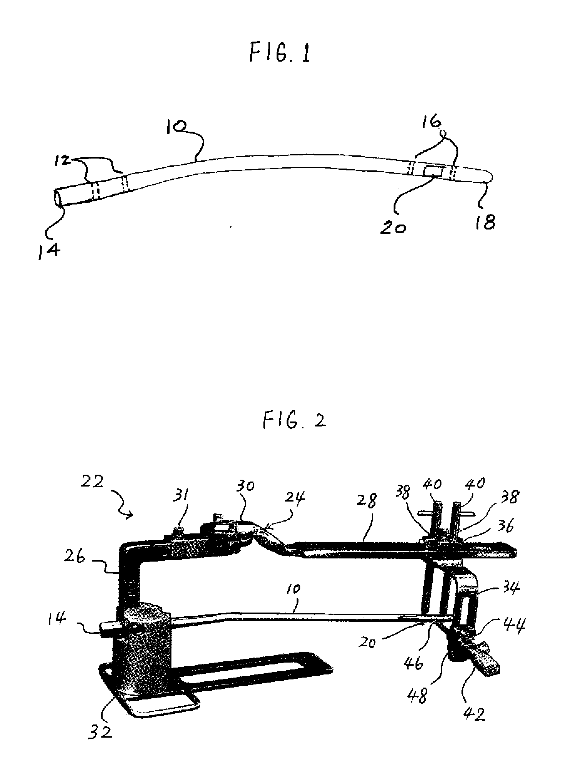
[0026]Referring now to FIG. 1, there is shown a perspective view of an exemplary intramedullary pin 10 that is to be emplaced within the bone of a patient. The intramedullary pin 10 is generally surgically emplaced within the tibia or femur bones to repair those bones and, in general, is comprised of, for example, a conductive metal, such as stainless steel, titanium and cobalt chrome.

[0027]In order to secure the intramedullary pin 10 within the bone of the patient, there are two holes 12 located at the proximal end 14 and two holes 16 located at the distal end 18. After the intramedullary pin 10 is surgically inserting into the bone, screws are passed through the holes 12, 16 to secure the intramedullary pin 10 within the bone. As such, since the intramedullary pin 10 is, at that time, located within the bone itself during the insertion of the screws, it is important that the physician be able to accurately locate the holes 12, 16 in order to properly align and insert the screws.

[0...


PUM


Abstract

A sensing device for determining the location of an intramedullary pin emplaced within the bone of a patient. The sensing device is useable with a frame that initially holds the intramedullary pin external of the patient and the sensing device used to contact a planar portion of the intramedullary pin to verify the orientation of predrilled holes in the intramedullary pin. The same set up is thereafter used with the intramedullary pin emplaced within the bone of a patient. The sensing device verifies the same location of the predrilled holes by contacting the same planar portion. The sensing device is an electrical continuity device that completes an electrical circuit when the distal end of the sensing device contacts the planar portion of the intramedullary pin, thereby activating an alerting device to notify the physician that the contact has been established and the predrilled holes are accurately located.

Description

FIELD OF THE INVENTION[0001]The present invention relates to a sensing device for use with a medical procedure and, more particularly, to a device to aid in the accurate location and orientation of an intramedullary pin.BACKGROUND[0002]In the healing of certain fractures in bones of a patient, particularly the femur and tibia bones, one common procedure is the surgical emplacement of intramedullary pins within the bones. In such procedure, the intramedullary pin is normally retained in the desired position within the bone by means of securing screws that pass through the bone and pre-drilled holes in the intramedullary pin at both the distal and proximal ends of the intramedullary pin.[0003]One of the difficulties, therefore, is to make sure that pin is in the exact desired location for receiving the screws since it is a blind procedure and the physician cannot actually see the intramedullary pin or the location of the pre-drilled holes in that pin.[0004]One of the present methods o...

Claims


Application Information

Patent Timeline
IPC IPC(8): A61B17/88
CPCA61B17/1725A61B17/1707
Inventor MARTINEZ, JAIME E.VILLAFANE, JOSE
Owner OSTEOAMERICA
Why Eureka
Try Eureka