Device for measuring a load at the end of a rope wrapped over a rod

Inactive Publication Date: 2007-11-22
HARNISCHFEGER TECH
View PDF5 Cites 91 Cited by
  • Summary
  • Abstract
  • Description
  • Claims
  • Application Information

AI Technical Summary

Benefits of technology

[0012]It is still another advantage of this invention to provide a measuring system of the foregoing type which can determine such calculations in a dynamic state and with an accuracy of within + or −0.1%.
[0013]It is another object of this invention to provide an improved system for measuring the load weight of large mining and lifting machinery, which system eliminates the need to try to compute dynamic force effects on the machine in order to get an accurate weight measurement.
[0014]It is yet another advantage of the present invention to provide a measuring system of the foregoing type which is adaptable for use with a wide variety of mining and lifting machinery.
[0015]It is yet another advantage of the present invention to provide a device that can automatically calibrate equipment, so the device accurately determines the location of a load carried by a mining and lifting machinery.

Problems solved by technology

It has been difficult to accurately calibrate strain gauges for a resultant force P with a non-stationary point of application.

Method used


Image

  • Device for measuring a load at the end of a rope wrapped over a rod
  • Device for measuring a load at the end of a rope wrapped over a rod
  • Device for measuring a load at the end of a rope wrapped over a rod

Examples


Embodiment Construction

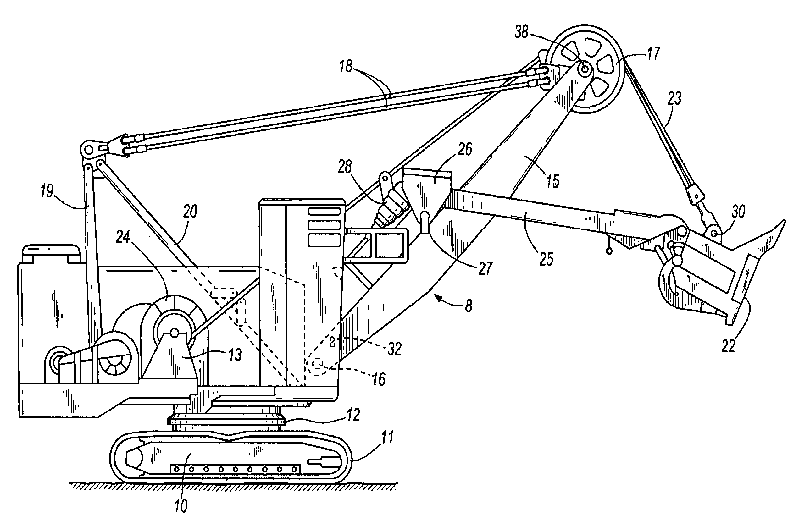
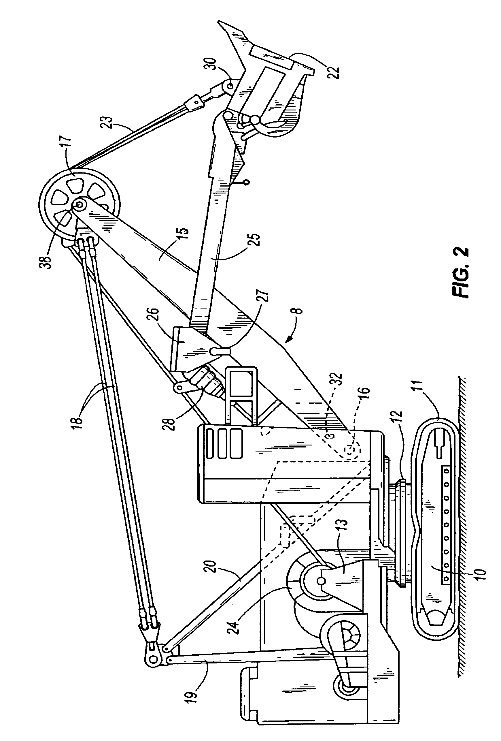
[0024]As described below and as illustrated in the drawings, the invention is a machine for raising and lowering a load, such as a hoisting machine 8 including a device 22 supported from a structure. More particularly, the machine can be a piece of large mining machine or an industrial crane, or any device for lifting a load. In this detailed description, a power shovel is described, and the device 22 for holding the material to be lifted is a dipper.

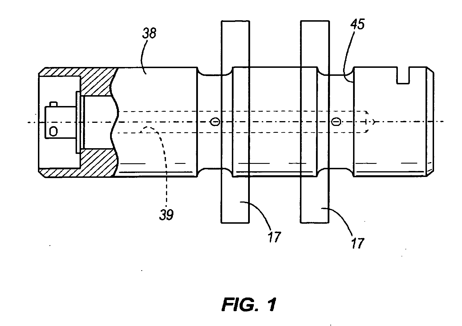
[0025]The power shovel 8 of FIG. 2 is of a well-known construction commonly referred to as an electric rope shovel. The shovel 8 comprises a mobile base 10 supported on drive tracks 11, and having supported thereon through a turntable 12, a platform in the form of a machinery deck 13. The turntable 12 permits full 360 degrees of rotation of the machinery deck relative to the base. A boom 15 is pivotally connected at a lower end 16 to the machinery deck 13. The boom 15 is held in a upwardly and outwardly extending relation to the deck by...


PUM


Abstract

A machine for raising and lowering a load, the machine including a platform, a boom attached at one end to the platform, a rod mounted transverse to the longitudinal axis of the boom on the other end of a boom, the rod having a central bore there through, with at least two strain gauges mounted therein and angled relative to each other, a hoist rope extending over the rod and having an end adapted to be attached to the load, and a mechanism connected to the at least two strain gauges for determining the angle of departure of the hoist rope from the rod and the amount of pull of the load on the hoist rope.

Description

BACKGROUND OF THE INVENTION[0001]This invention is directed to devices for measuring the weight of a load at the end of a rope wrapped over a rod.[0002]It is known to measure the weight of a load at the end of a rope wrapped or trained over a rod by using four strain gauges configured as a bridge circuit glued inside a central bore in a rod. This is an optimum configuration to measure a force applied in a vertical direction only. When the force to be measured has a constant angle relative to the strain gauge, one set of gauges has been used.[0003]The calibration procedure used in this instance is as follows.[0004]1. Place the instrumented rod in a calibration fixture that applies a load in the vertical direction.[0005]2. Apply an increasing load in a series of load steps. The maximum load is the expected maximum load the sensor will see. Measure the strain gauge bridge output at each of these load steps.[0006]3. Repeat step 2 for decreasing load steps to zero load.[0007]4. A curve i...

Claims


Application Information

Patent Timeline
IPC IPC(8): E02F3/48
CPCE02F3/30E02F9/006G01L5/101G01G3/141G01G19/18E02F9/24G01G23/01
Inventor CLAXTON, RICHARD L.
Owner HARNISCHFEGER TECH
Why Eureka
Try Eureka