Catching tool for baseball or softball

Inactive Publication Date: 2009-12-10
MIZUNO CORPORATION
View PDF12 Cites 7 Cited by
  • Summary
  • Abstract
  • Description
  • Claims
  • Application Information

AI Technical Summary

Benefits of technology

[0009]The present invention has been made to solve the above-mentioned problems, and an object of the invention is to provide a catching tool for baseball or softball about which at the time of catching a

Problems solved by technology

However, the first and second resin layers may not be

Method used


Image

  • Catching tool for baseball or softball
  • Catching tool for baseball or softball
  • Catching tool for baseball or softball

Examples


embodiment 1

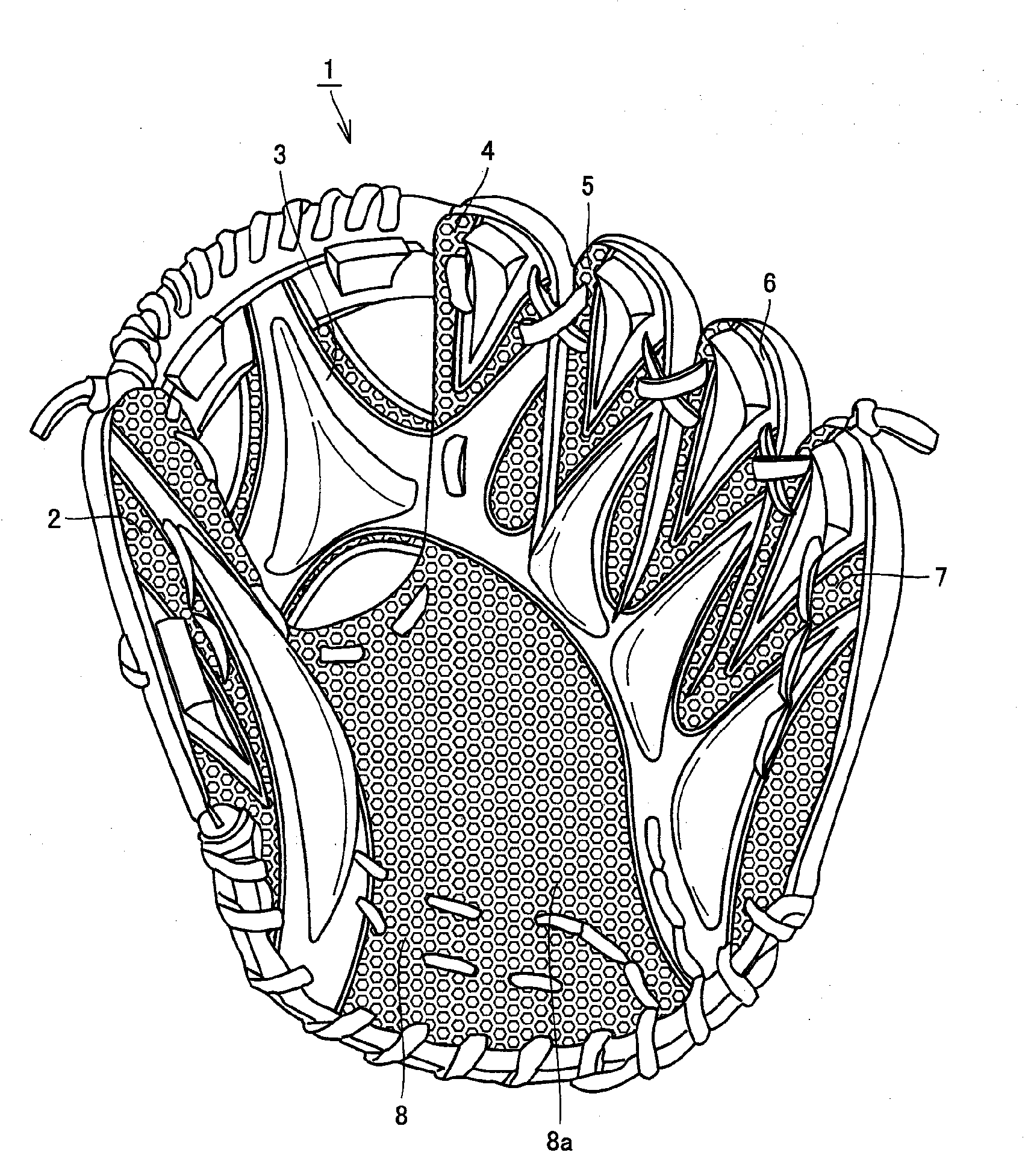
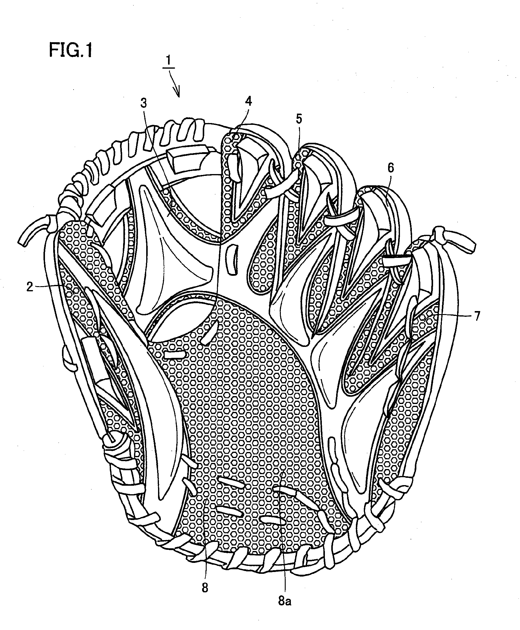
[0036]FIG. 1 is a front view of a catching tool for baseball or softball according to Embodiment 1 of the invention. In Embodiment 1 illustrated in FIG. 1, a glove for baseball or softball is illustrated as the catching tool. However, the invention is applicable to a catching tool other than gloves as far as the catching tool is a tool capable of catching a ball, example of the tool including a catcher's mitt and a first baseman's mitt.

[0037]A catching tool 1, which is the catching tool for baseball or softball of Embodiment 1, is provided with, for example, an outer leather and an inner leather inserted into the outer leather. However, such an inner leather may be not given, so that the catching tool may be made only of an outer leather.

[0038]The outer leather has a ball receiving portion for covering the palm side of a person who is to have the tool on (i.e., a user) when the user has the tool on, and containing a ball receiving surface for receiving a ball, and a back portion for...

embodiment 2

[0072]With reference to FIGS. 6 and 7, the following will describe Embodiment 2 of the invention, and a modified example thereof. FIG. 6 is a plan view illustrating ball receiving member 8 of a catching tool according to Embodiment 2 of the invention, and FIG. 7 is a plan view illustrating ball receiving member 8 in a modified example of the catching tool of Embodiment 2.

[0073]As illustrated in FIG. 6, in Embodiment 2, only a mesh-form resin layer 9 that has a small thickness is formed over the whole of the surface of ball receiving portion 8a; thus, small-width resin layers 12, convex regions 11 and large-width resin layers 10 are not given. In the case of Embodiment 2, resin layer 9 is made of soft resin and openings 9a are made in resin layer 9 and over the whole thereof. The thickness of resin layer 9 is preferably made as small as about 0.5 to 1.5 mm.

[0074]In the case of Embodiment 2 also, openings 9a are made in resin layer 9; therefore, when a ball is caught, catching tool 1 ...

embodiment 3

[0079]With reference to FIGS. 8 and 9, Embodiment 3 of the invention and a modified example thereof will be described hereinafter. FIG. 8 is a plan view illustrating ball receiving member 8 of a catching tool according to Embodiment 3 of the invention, and FIG. 9 is a plan view illustrating ball receiving member 8 in a modified example of the catching tool of Embodiment 3.

[0080]As illustrated in FIG. 8, in Embodiment 3, large-width resin layers 10 are formed at intervals on the surface of ball receiving portion 8a. Small-width resin layers 12 are made on both sides of each of large-width resin layers 10. The thickness of large-width resin layers 10 may be varied by, for example, arranging the same convex regions 11 as in Embodiment 1 in large-width resin layers 10.

[0081]Large-width resin layers 10 and small-width resin layers 12 may be the same or different in thickness, raw material, hardness, and other characteristics. For example, large-width resin layers 10 may be thicker than s...


PUM


Abstract

Disclosed is a catching tool for baseball or softball including a ball receiving portion covering the palm side of a user's hand when wearing the tool and containing a ball receiving surface for receiving a ball, a resin layer that is selectively formed on the surface of the ball receiving portion and can be deformed along a surface of the ball when catching the ball, and a back portion for covering the back of the user's hand. On the ball receiving portion, various resin layers may be optionally formed, examples of the resin layers including a large-width resin layer, and a small-width resin layer having a convex regions.

Description

BACKGROUND OF THE INVENTION[0001]1. Field of the Invention[0002]The present invention relates to a catching tool for baseball or softball, more specifically, a catching tool for baseball or softball wherein a resin layer is formed on a surface of a ball receiving portion for covering the palm side of a person who is to have the tool on.[0003]2. Description of the Background Art[0004]Hitherto, known has been a catching tool wherein a coating film made of synthetic resin is formed on the entire surface of a ball catching surface in order to restrain a ball from dropping down when the ball is caught. Such a catching tool is described in, for example, Japanese Patent Laying-Open Nos. 58-221901 and 61-143081.[0005]Moreover, Utility Model Laying-Open No. 63-186474 describes a glove for baseball wherein an anti-slipping body made of an elastomer is arranged in a ball catching surface to catch a hit ball or the like certainly, and Japanese Patent Laying-Open No. 2006-239402 describes a catc...

Claims


Application Information

Patent Timeline
IPC IPC(8): A63B71/14
CPCA63B71/143
Inventor KUME, KAZUHIROONO, TAKASHI
Owner MIZUNO CORPORATION
Why Eureka
Try Eureka