
Shower base

a shower base and shower technology, applied in the field of shower bases, can solve problems such as the complete cessation of water flow in the recirculation circui

Inactive Publication Date: 2009-12-10
QUENCH SOLUTIONS
View PDF4 Cites 13 Cited by
  • Summary
  • Abstract
  • Description
  • Claims
  • Application Information

AI Technical Summary

Benefits of technology

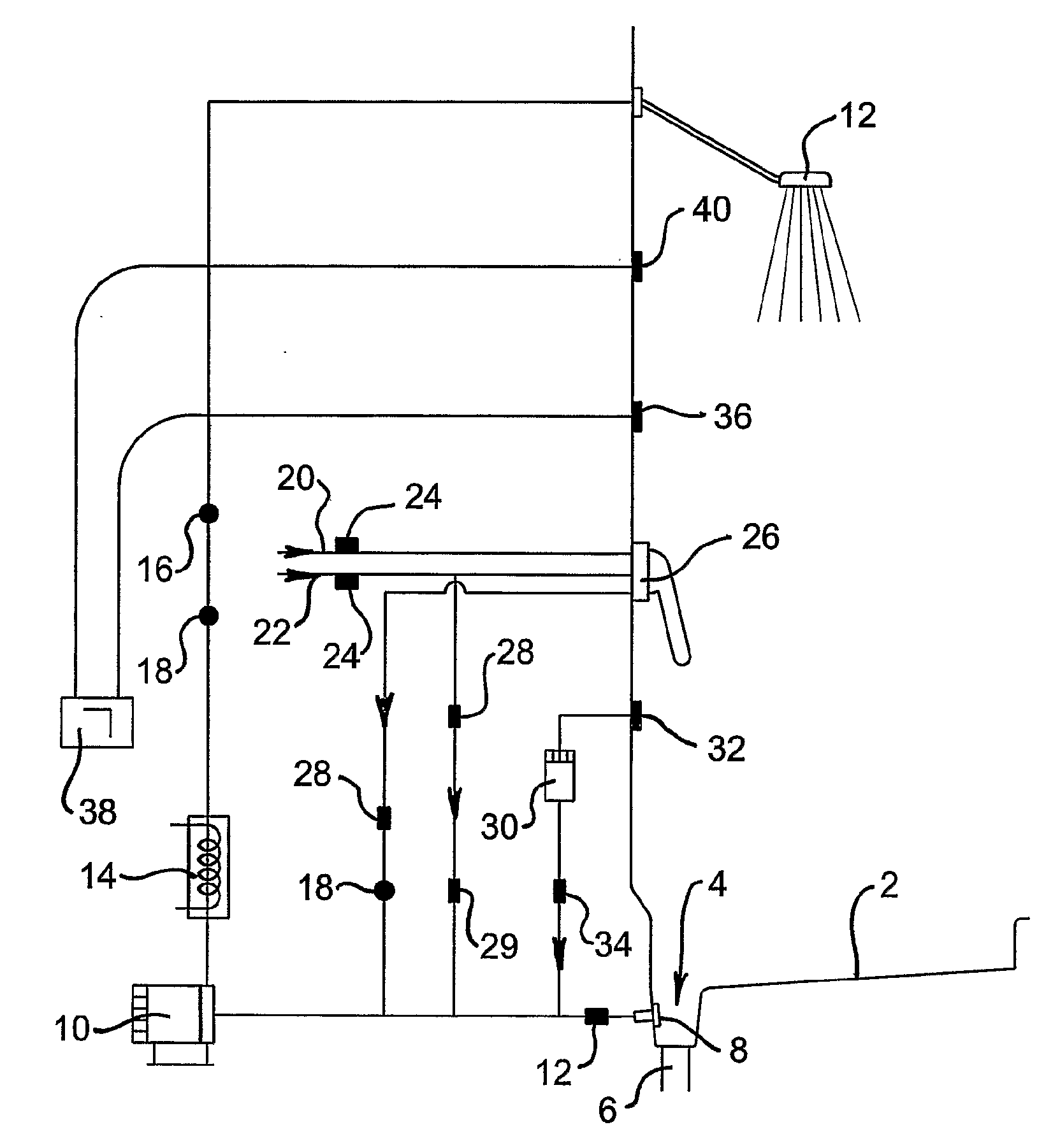
[0010]Applicant proposes that the use of a reservoir minimizes the amount of water required to be used in a recirculation shower apparatus. As will be understood, to start water moving through a recirculation circuit a minimum level of water must be available to the system. The minimum volume includes water necessary to fill all components of the circuit (for example pipes, valves, fittings, pumps etc), and also water necessary to ensure that the intake to the recirculation pump is covered with water. It is necessary to ensure that sufficient water is available to the intake side of the pump such that air, or at least a significant volume of air, is not drawn into the system. The presence of air can lead to cavitation in the pump causing complete cessation of water flow in the recirculation circuit. The presence of a reservoir about the first outlet means that only a small volume of water is necessary to cover the outlet, thereby decreasing the minimum volume of water required to run the shower in recirculation mode.
[0013]Alternatively, to increase the efficiency of water collection from the floor the reservoir may extend distal to the first outlet. In one embodiment, the reservoir extends along one or more edges of the shower base. In this embodiment, the water may run into areas of the reservoir distal to the first outlet, but then further run to an area of the reservoir proximal to the first outlet.
[0017]In one form of the invention the first outlet is positioned in the reservoir such that water passes through the outlet in a non-vertical direction. Preferably, the first outlet is positioned such that water passes through the outlet in a substantially horizontal direction. This may be achieved by positioning the outlet on a substantially vertical wall of the reservoir. As discussed in the Background section, consumers are averse to being exposed to water that has entered a standard drain in the floor of a shower base. The use of a reservoir having an outlet on a substantially horizontal wall feeding the recirculation pump allows the user to assure them that the recirculating water enters only the inlet that feeds the recirculation pump and does not enter the drain. Furthermore, the horizontal exit of water provides the user confidence that water used for recirculation does not pool, as may be the case where the water exits vertically as occurs with a traditional drain hole in the floor of a shower base.
[0024]The present invention may provide advantages in respect to decreasing energy requirements for heating water used in showering. When in recirculation mode, further water is not admitted to the circuit, with water collected from the reservoir providing all water necessary to supply the shower head. In this embodiment of the invention, it is therefore not necessary to heat water from ambient temperature, to a temperature comfortable for showering. It will be appreciated that increased advantage may be gained where the ambient temperature is low (for example, 2 or 3 degrees Celsius) in which situation large amounts of energy are required to heat water up to a temperature comfortable for showering.
[0028]Thus, based upon the above calculations a shower of the present invention operating in recirculation mode provides a theoretical energy saving of around 75% where the ambient temperature is 20 degrees Celsius. If the inlet water temperature supplying a conventional shower was at 1 degree Celsius then the theoretical energy saving gained by a shower of the present invention would be around 87%. Thus, even greater energy savings are theoretically realized when operating a shower of the present invention in a cold climate.

Problems solved by technology

The presence of air can lead to cavitation in the pump causing complete cessation of water flow in the recirculation circuit.

Method used


Image

  • Shower base
  • Shower base
  • Shower base

Examples


Embodiment Construction

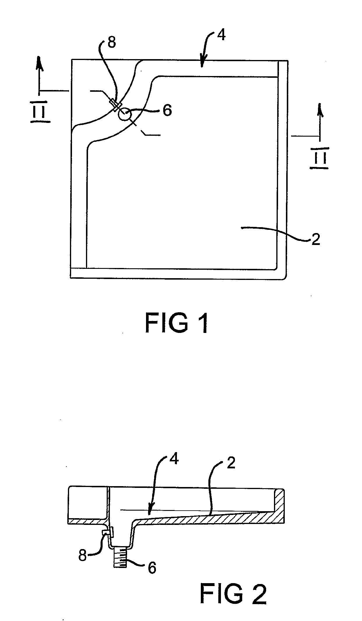
[0034]FIGS. 1 and 2 illustrate a shower base structure according to the invention in plan view and cross-sectional view respectively. The base structure includes a substantially planar floor area 2 with a reservoir 4 abutting two sides of the floor. The reservoir 2 includes an outlet 6 to waste and an outlet 8 to the recirculation pump. While not apparent from the drawings, the floor area is sloped toward the reservoir. Furthermore, the floor of the reservoir is sloped toward the outlets 6 and 8 such that water falling on the floor runs to the nearest portion of the reservoir. Once in the reservoir, the water is then directed to a central region of the reservoir where outlets 6 and 8 are positioned.

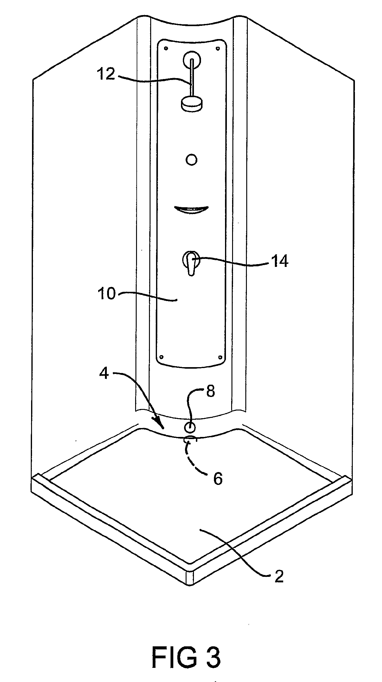
[0035]FIG. 3 illustrates a corner-mounted shower system according to the invention including a substantially planar floor area 2 with a reservoir 4 abutting two sides of the floor area. The reservoir 2 includes an outlet 6 to waste and an outlet 8 to the recirculation. The central pillar ...


PUM


Abstract

The present invention provides a base structure for a shower, the shower having a water recirculation circuit, the base including a substantially planar floor and a reservoir, the reservoir including a first outlet for admitting water to be used by the recirculation circuit, and a second outlet for admitting water to be sent to waste, wherein in use where the passage of water to waste is obstructed, water contacting the floor runs into the reservoir to form a pool of sufficient depth to substantially cover the first outlet. Use of the structure may result in water and energy savings.

Description

FIELD OF THE INVENTION[0001]The present invention relates to a base structure for use in shower cubicles. In particular, the invention provides a shower base for use in showers that use water recirculation to save water.BACKGROUND TO THE INVENTION[0002]The issue of water conservation is becoming increasingly important given the effects of population and climate change on the world's water supplies. Significant volumes of water are wasted in the bathroom where many liters are sent to waste in the course of bathing and showering. While a shower is often considered to be less wasteful of water than a bath, this assumption may be valid only where the shower is of short duration. Many people enjoy the relaxing effects of a shower, and can often spend significant periods of time under running water. Many also attend to other tasks such as dental care, exfoliation, depilation and the like during showering. The extended time spent in the shower leads to wastage of significant amounts of wat...

Claims


Application Information

Patent Timeline
IPC IPC(8): A47K3/00
CPCA47K3/40E03C2001/005E03C1/00
Inventor GAY, BRIAN
Owner QUENCH SOLUTIONS
Learn More