Anti-siphon valve with freeze protection

a technology of anti-siphon valve and freeze protection, which is applied in the direction of functional valve types, service pipe systems, drawing-off water installations, etc., can solve the problems of serious damage to the components of the irrigation system, failure to “do it-yourself” winterizing by homeowners, and out-of-training technicians, etc., to facilitate quick inspection of the ball valve, facilitate service, and simplify the arrangement

Active Publication Date: 2018-02-20
TOWSLEY BRYAN L
View PDF12 Cites 1 Cited by
  • Summary
  • Abstract
  • Description
  • Claims
  • Application Information

AI Technical Summary

Benefits of technology

[0014]A backflow prevention valve, the backflow prevention valve having a vertical inlet, a horizontal outlet, and three drainage nipples to allow drainage without the use of compressed air, the backflow prevention valve further having a bonnet and lower poppet valve that eliminates components found in known devices, and results in a simpler arrangement that is easier to service.
[0015]According to a preferred embodiment of the invention, the polymer plug is made of a translucent acrylic polymer. The polymer plug will preferably include a threaded male portion that is adapted for treaded attachment to the side pressure relief port of the ball valve. Additionally, the polymer plug will preferably include a translucent head that will have a generally flat top surface and at least two parallel sides that are adapted for accepting a spanner wrench or for engagement with a pair of pliers. The male portion of the polymer plug will preferably include a counter bore that extends along the center of the male portion towards the top surface. The counter bore will allow any water that is trapped in the ball valve to travel towards the top surface, which will facilitate quick inspection of the ball valve to determine whether the ball valve is holding water and needs to be drained.
[0016]Additionally, it is contemplated that the ball valves will include bushings and body design that will minimize the amount of water that can remain trapped between the ball and the body of the valve. According to a preferred example of the invention, it is contemplated that the bushings used with the ball valves of the disclosed invention will be configured fill much of the space found between the spherical gate of the ball valve and the body of the ball valve. This configuration will minimize the amount of water that can be trapped in this space, and thus minimize the possibility of rupturing the body of the ball valve due to freezing of trapped water. Additionally, it is contemplated that the disclosed invention will be equipped with a polymer plug that will be aligned with the passage in the spherical gate when the ball valve is in the closed position. This arrangement will allow freezing water that is trapped in the passage to expand against the polymer plug, pushing the plug from the body of the valve, and thus alleviating pressure that may lead to damage to the body of the valve. Still further, it is contemplated that the sacrificial polymer plug will be made from a transparent or translucent material, which will allow the homeowner to visually inspect the plug to verify if there is water trapped in the ball valve.

Problems solved by technology

However, it often happens that sudden cold fronts strike very quickly in fall and spring months, which results in an immediate need for winterization of a very large number of irrigation systems in hopes of avoiding freezing of water trapped in the irrigation system.
This sudden need for assistance from trained technicians outstrips the supply of available technicians, and results in failed attempts at “do-it-yourself” winterizing by homeowners.
The result is that water that is trapped in the irrigation system freezes and causes serious damage to components of the irrigation system.
Homeowners can typically locate and shut off the main water valve to their irrigation system, but are often unable to drain water that remains in the backflow devices that are part of the irrigation system.
Similarly, homeowners may not have the equipment needed to thoroughly remove potentially harmful levels of water that may remain trapped in valves, and particularly in ball valves that are commonly used in irrigation systems.
As a consequence of the inadequate drainage, the backflow devices are then damaged or destroyed by the expansion of freezing water trapped in the devices.

Method used


Image

  • Anti-siphon valve with freeze protection
  • Anti-siphon valve with freeze protection
  • Anti-siphon valve with freeze protection

Examples


Embodiment Construction

[0030]While the invention will be described and disclosed here in connection with certain preferred embodiments, the description is not intended to limit the invention to the specific embodiments shown and described here, but rather the invention is intended to cover all alternative embodiments and modifications that fall within the spirit and scope of the invention as defined by the claims included herein as well as any equivalents of the disclosed and claimed invention.

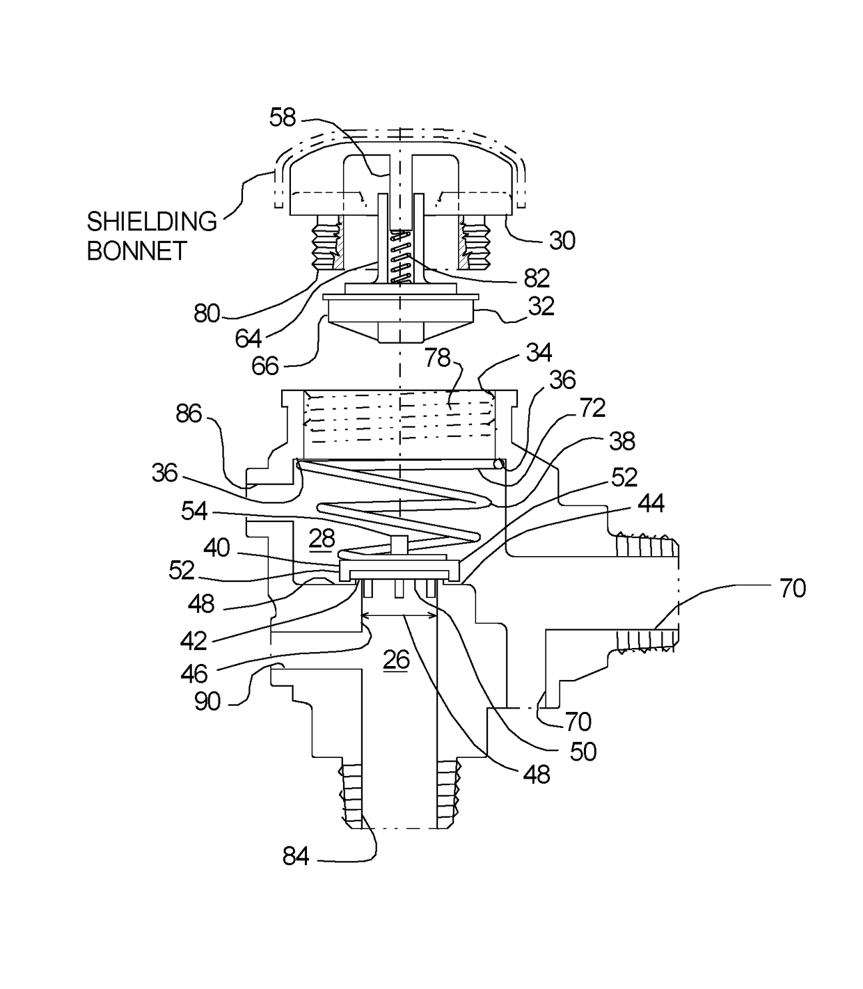
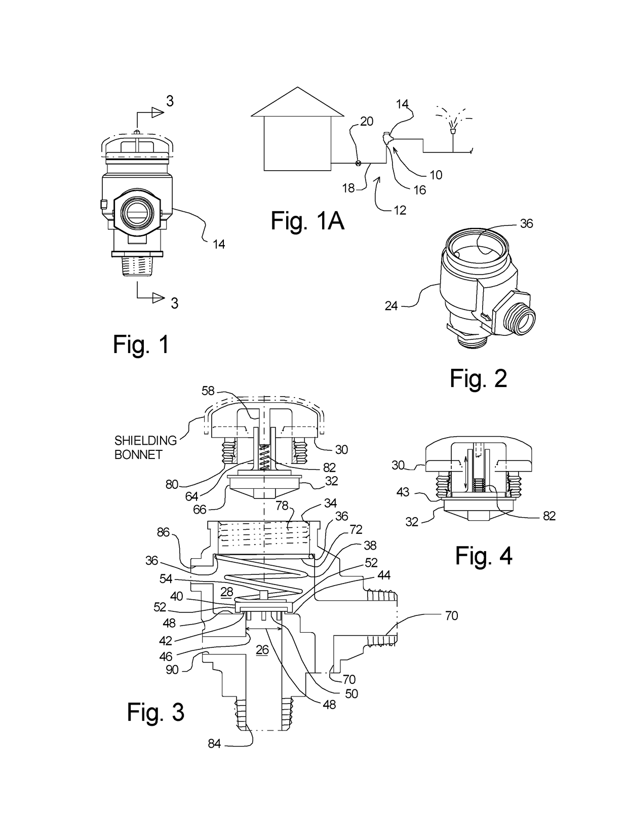
[0031]Turning now to FIGS. 1 and 1A where an anti-backflow system 10 for an irrigation system 12 has been illustrated. The anti-backflow system 10 allows pressure equalization of the pressure within backflow prevention valve 14 and the surrounding atmosphere. As can be understood from FIG. 1A, it is contemplated that the backflow prevention valve 14 will be installed from the upper end 16 of a generally vertical water supply line 18. The water supply line 18 is controlled through a supply valve 20, which allows wate...


PUM


Abstract

An anti-siphon system for use with an irrigation system, such as lawn sprinkling system is disclosed. The system includes a backflow prevention valve with a bonnet- and poppet valve system with a conical spring that biases a lower poppet valve head, and engages the valve body. The use of the conical spring simplifies the mechanism, while providing reliable backflow prevention.

Description

REFERENCE TO RELATED APPLICATIONS[0001]This application claims the benefit of my U.S. non provisional application titled ANTI-SIPHON VALVE WITH FREEZE PROTECTION, having Ser. No. 14 / 507,716, filed Oct. 6, 2014, now U.S. Pat. No. 9,504,214, incorporated herein by reference.BACKGROUND OF THE INVENTION(a) Field of the Invention[0002]This application relates to an anti-siphon valve system, and more particularly for a system that facilitates winterization of the valve system and which includes an improved anti-siphon valve system.(b) Discussion of Known Art[0003]Anti-siphon valves are widely used with irrigation systems. A popular anti-siphon valve is used as part of FEBCO Series 765 Pressure Vacuum Breakers. These anti-siphon devices are discussed in my U.S. Pat. No. 7,934,515, (“the '515 patent”) issued May 3, 2011, and which is incorporated herein by reference in its entirety.[0004]While the arrangements discussed in my '515 patent perform as expected, these devices are designed for s...

Claims


Application Information

Patent Timeline
Patent Type & Authority Patents(United States)
IPC IPC(8): E03C1/10F16K24/00A01G25/16F16K24/06F16K24/02
CPCA01G25/16E03C1/102E03C1/104F16K24/06Y10T137/3331Y10T137/3149F16K24/02E03B7/12E03B9/027E03B9/14E03C1/10
Inventor TOWSLEY, BRYAN L.
Owner TOWSLEY BRYAN L
Why Eureka
Try Eureka