
Integrated energy system for whole home or building

a technology of integrated energy system and whole house, applied in sustainable buildings, lighting and heating apparatus, machine operation mode, etc., can solve the problems of increasing the cost of fossil fuels, and prior alternative energy systems that have evolved piecemeal

Inactive Publication Date: 2009-12-10
WATTS THERMOELECTRIC
View PDF41 Cites 45 Cited by
  • Summary
  • Abstract
  • Description
  • Claims
  • Application Information

AI Technical Summary

Benefits of technology

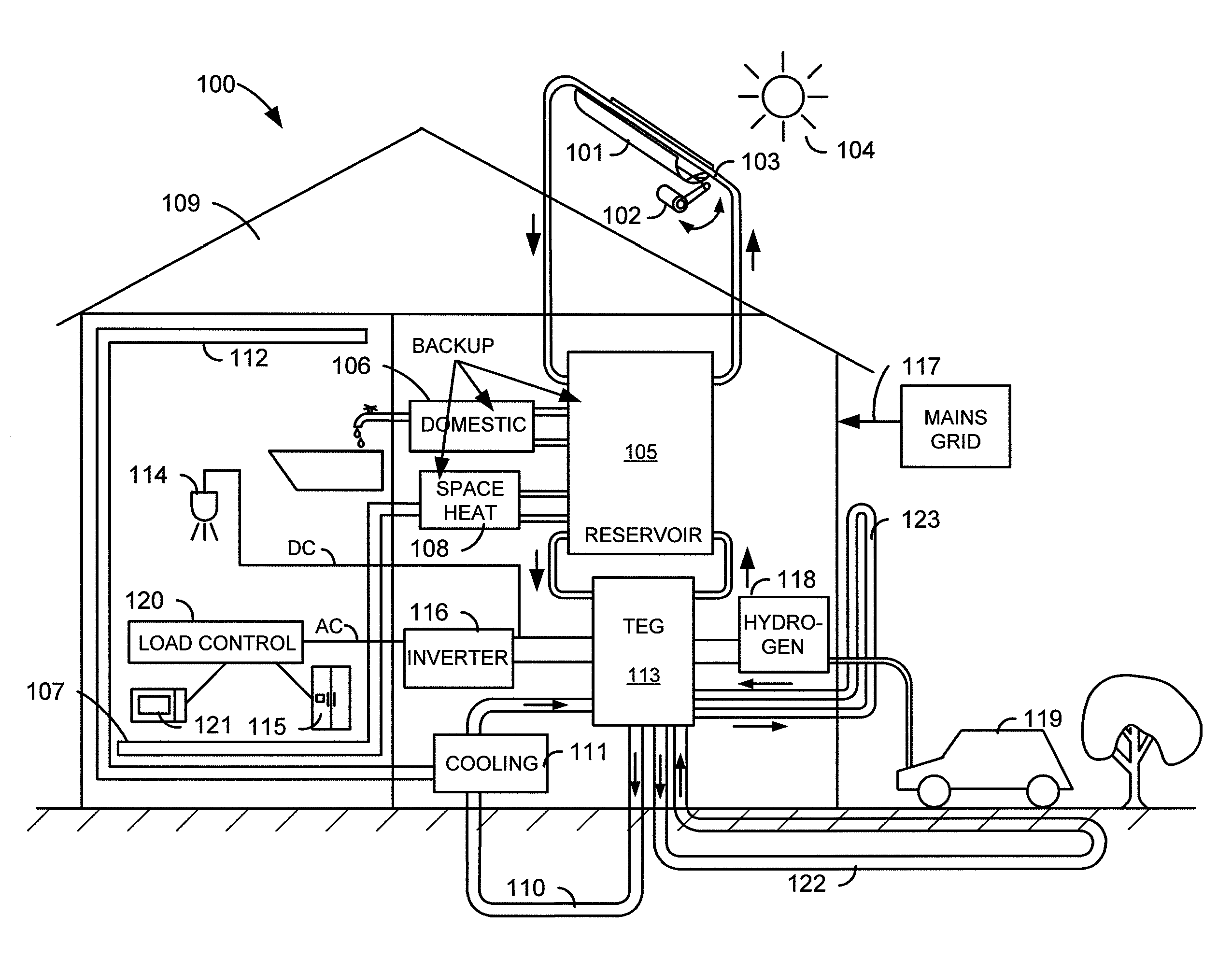
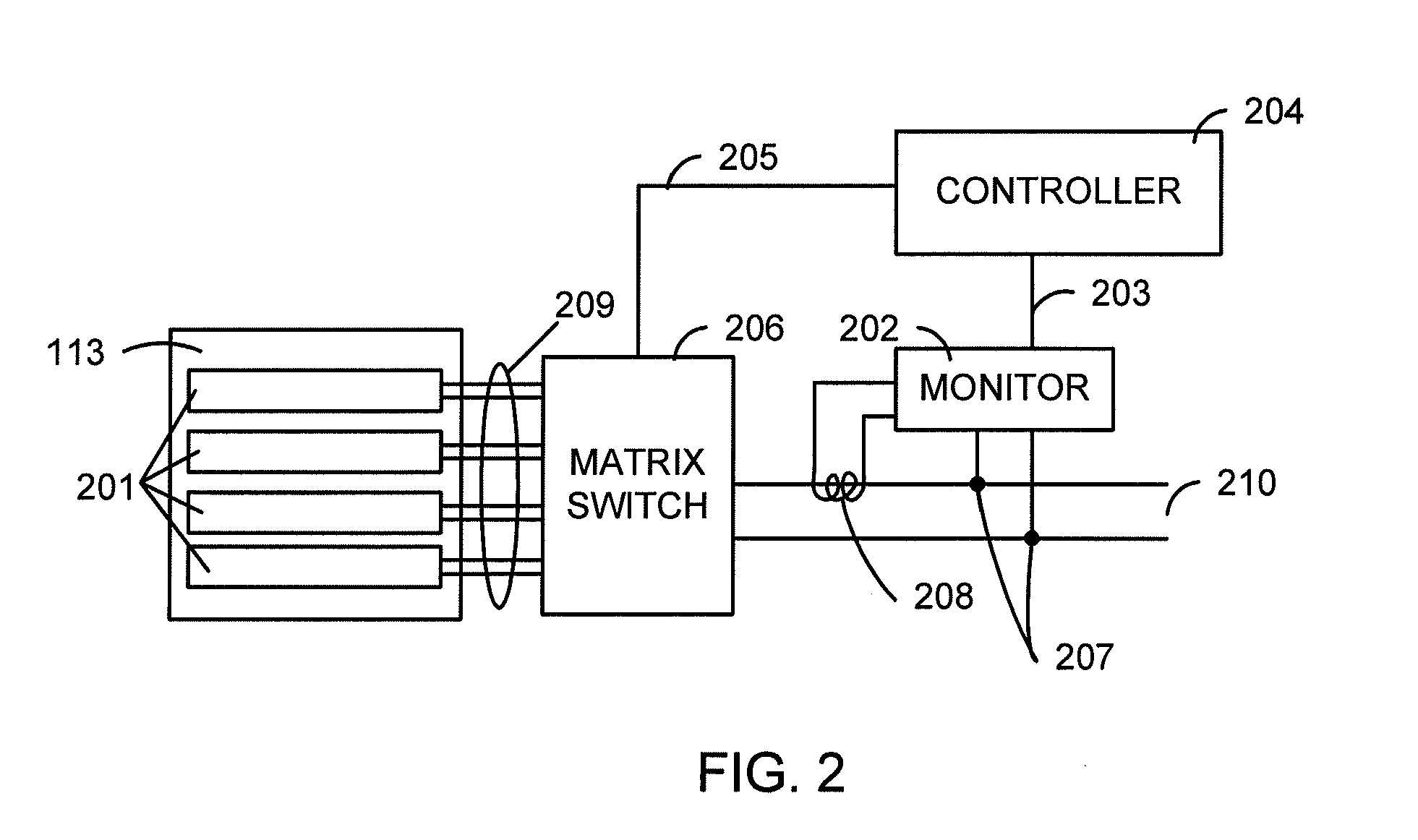
[0014]In some embodiments, the method further comprises circulating at least some of the cooling fluid through a hydronic cooling loop, providing space cooling to at least one space in the building. The method may comprise generating hydrogen using electrical energy generated by the thermoelectric generator. In some embodiments, the method comprises storing, separately from the reservoir of thermal energy, water designated for domestic hot water use. In some embodiments, the method further comprises heating the water designated for domestic hot water use with heat from the reservoir of thermal energy. In some embodiments, the method comprises dynamically configuring, using a thermoelectric generator controller, interconnections of thermoelectric modules within the thermoelectric generator. In some embodiments, the method comprises temporarily preventing the operation of at least one electrical load based in part on the amount of electrical power being consumed by other loads. In some embodiments, circulating the cooling fluid through and environment-coupled piping loop comprises circulating the cooling fluid through and earth-coupled piping loop.

Problems solved by technology

Many of these traditional energy systems depend on non-renewable and ever-more-expensive fossil fuels.
However, prior alternative energy systems have evolved piecemeal.
While the day-to-day operating cost of a photovoltaic system is low, these systems typically have a high installation cost, and the batteries have a finite life, requiring expensive periodic replacements.
Battery systems also are typically oversized, as the life of the batteries is optimized by avoiding discharges of more than 20 percent of the stored energy from the batteries.

Method used


Image

  • Integrated energy system for whole home or building
  • Integrated energy system for whole home or building
  • Integrated energy system for whole home or building

Examples


Embodiment Construction

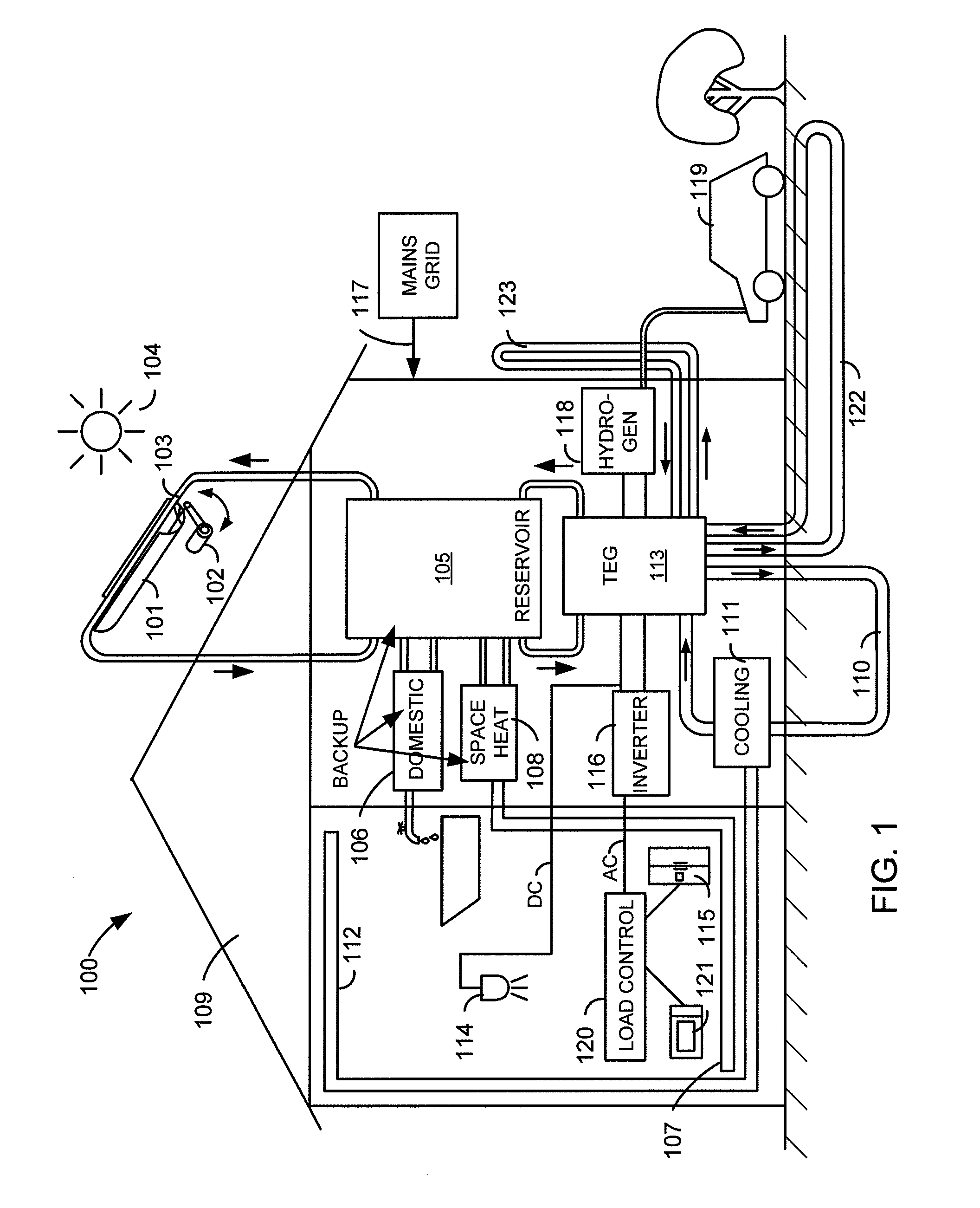
[0017]An integrated energy system for a home or other building utilizes a heated reservoir for energy storage. The reservoir is mainly heated by one or more solar collectors. The system also includes at least one environment-coupled piping loop through which a cooling fluid is circulated such that heat is exhausted from the cooling fluid to the environment. The thermal energy from the reservoir and the cooling fluid are then used in an integrated set of systems that provide space heating, space cooling, and electrical generation. Electricity is generated by a thermoelectric generator that exploits the temperature differential between the reservoir and the cooling fluid. The system may include heating and storage for domestic hot water, and may use excess power for hydrogen production. Backup heating and electrical systems may be provided for.

[0018]The ensuing description provides preferred exemplary embodiment(s) only, and is not intended to limit the scope, applicability or configu...


PUM

PropertyMeasurementUnit
temperatureaaaaaaaaaa
cooling capacityaaaaaaaaaa

Abstract

An integrated energy system for a home or other building utilizes a heated reservoir for energy storage. The reservoir is mainly heated by one or more solar collectors. The system also includes an environment-coupled piping loop through which a cooling fluid is circulated such that heat is exhausted from the cooling fluid to the environment. The thermal energy from the reservoir and the cooling fluid are then used in an integrated set of systems that provide space heating, space cooling, and electrical generation. Electricity is generated by a thermoelectric generator that exploits the temperature differential between the reservoir and the cooling fluid. The system may include heating and storage for domestic hot water, and may use excess power for hydrogen production. Backup heating and electrical systems may be provided for.

Description

[0001]This application claims priority to provisional application 61 / 060,377, filed Jun. 10, 2008 and titled “Combined Heat and Power and Hydrogen Generation for Whole Home or Building with Ground Heat Exchanger Using Thermoelectric Seebeck Modules,” the entire disclosure of which is hereby incorporated by reference herein for all purposes.CROSS REFERENCE TO RELATED APPLICATIONS[0002]This application is related to U.S. patent application Ser. No. ______ (Attorney docket number 027483-000300US), titled “Automatic Configuration of Thermoelectric Generation System to Load Requirements” and to U.S. patent application Ser. No. ______ (Attorney docket number 027483-000500US), titled “Thermoelectric Generator”, both having the same inventor as the present application and filed Jun. 10, 2009. The disclosures of those two applications are hereby incorporated herein in their entirety for all purposes. Provisional U.S. patent application 60 / 306,274, titled “Combination outdoor portable heating...

Claims


Application Information

Patent Timeline
Patent Type & Authority Applications(United States)
IPC IPC(8): F25B29/00F24J2/04F24J2/46F24J2/42F24J2/00H01L35/30H10N10/01H10N10/80F24S90/00H10N10/00H10N10/13H10N10/17
CPCH01L35/00Y02B10/20F24J2/42H01L35/30Y02E10/40Y10T29/49002F24S90/00H10N10/00H10N10/13
Inventor WATTS, PHILLIP C.
Owner WATTS THERMOELECTRIC
Learn More