Inertial drive actuator

Inactive Publication Date: 2009-12-10
OLYMPUS CORP
View PDF7 Cites 4 Cited by
  • Summary
  • Abstract
  • Description
  • Claims
  • Application Information

AI Technical Summary

Benefits of technology

[0009]The present invention is made in view of the abovementioned circumstances and an object of the present invention is to provide an inertial drive actuator in which

Problems solved by technology

However, in the mobile table 200 in FIG. 9, since a mechanism to be moved in X-axis direction and a mechanism to be moved in Y-axis direction are formed independently, the number of comp

Method used


Image

  • Inertial drive actuator
  • Inertial drive actuator
  • Inertial drive actuator

Examples


first embodiment

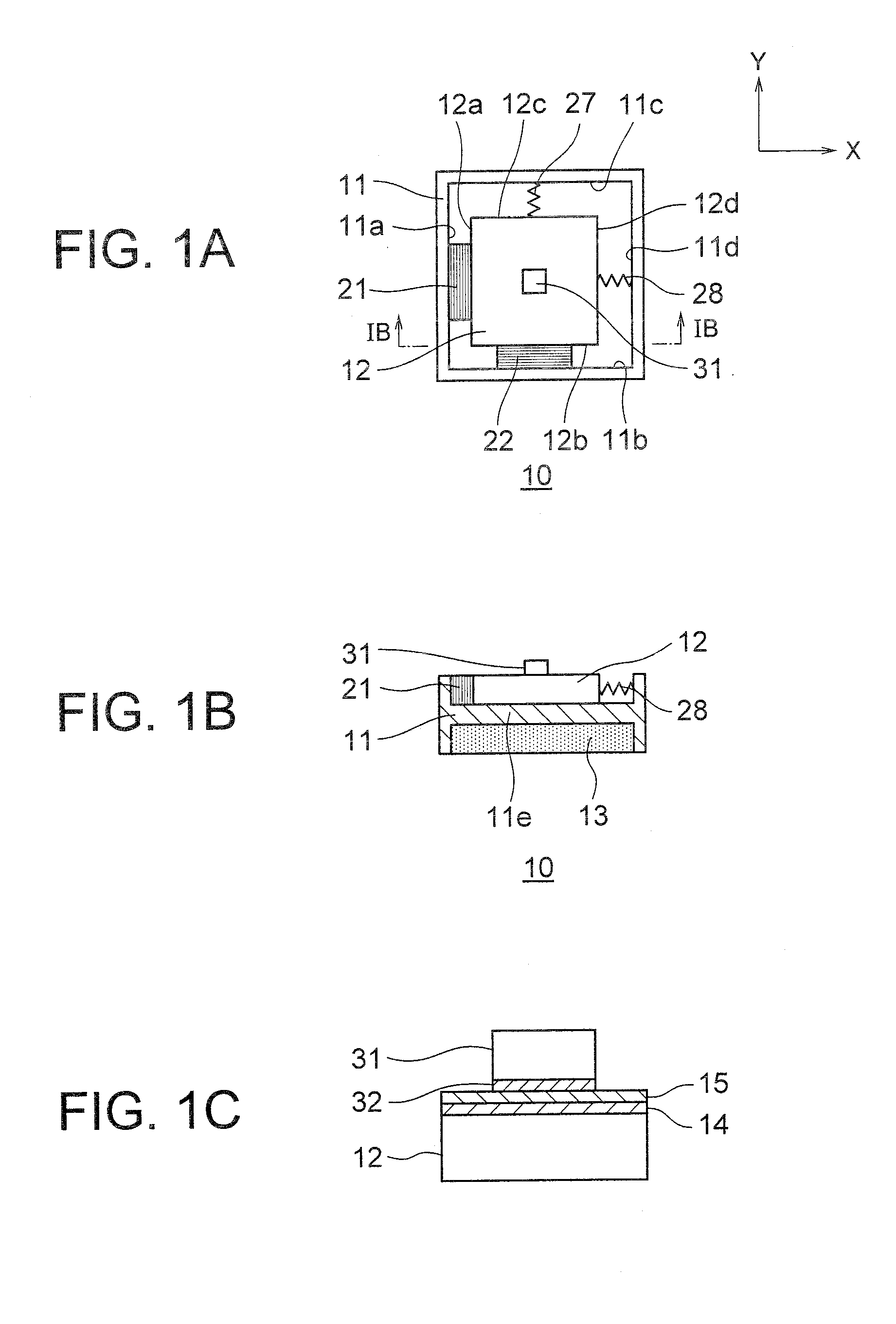
[0036]An inertial drive actuator 10 according to a first embodiment of the present invention will be described below while referring to diagrams from FIG. 1A to FIG. 5D. Here, FIG. 1 is a plan view showing a structure of the inertial drive actuator 10 according to the first embodiment, FIG. 1B is a cross-sectional view taken along a line IB-IB in FIG. 1A, and FIG. 1C is a partially enlarged view of a mobile object 31 and a vibration substrate 12 in FIG. 1A.

[0037]As shown in FIG. 1A and FIG. 1B, the inertial drive actuator 10 includes a fixed member 11, piezoelectric elements 21 and 22 as a first displacement generating means (a first displacement generating mechanism) and a second displacement generating means (a second displacement generating mechanism) respectively, the mobile object 31 and the vibration substrate 12 displaceably mounted on an intermediate plate lie of the fixed member 11. Moreover, a permanent magnet 13 is disposed at a lower side of the intermediate plate lie of...

second embodiment

[0065]Next, an inertial drive actuator 40 according to a second embodiment of the present invention will be described below while referring to FIG. 6A and FIG. 6B. FIG. 6A is a plan view showing a structure of the inertial drive actuator 40 according to the second embodiment, and FIG. 6B is a cross-sectional view taken along a line VIB-VIB in FIG. 6A.

[0066]As shown in FIG. 6A, in the inertial drive actuator 40 according to the second embodiment, one end of a piezoelectric element 51 (displacement generating mechanism) is disposed adjacent to a left end of the lower-side surface 12b of the vibration substrate 12, and one end of a piezoelectric element 52 (displacement generating mechanism) is disposed adjacent to a substantial central of the lower-side surface 12b of the vibration substrate 12.

[0067]The other end of the piezoelectric element 51 and the other end of the piezoelectric element 52 are disposed adjacent to the inner-side surface 11b of the fixed member 11. Here, the piezo...

third embodiment

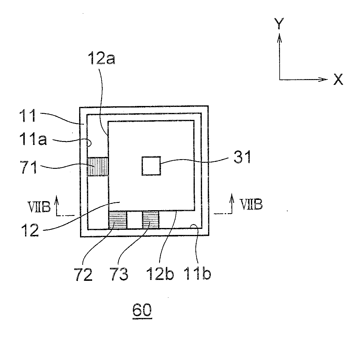
[0071]Next, an inertial drive actuator 60 according to a third embodiment of the present invention will be described below while referring to FIG. 7A and FIG. 7B. FIG. 7A is a plan view showing a structure of the inertial drive actuator 60 according to the third embodiment, and FIG. 7B is a cross-sectional view taken along a line VIIB-VIIB in FIG. 7A.

[0072]As shown in FIG. 7A, in the inertial drive actuator 60 according to the third embodiment, piezoelectric elements 72 and 73 (displacement generating mechanism) are disposed similarly as the piezoelectric elements 51 and 52 according to the second embodiment. Furthermore, a piezoelectric element 71 (displacement generating mechanism) is arranged such that one end thereof is adjacent to a substantial center of the left-side surface 12a of the vibration substrate 12, and the other end of the piezoelectric element 71 is arranged adjacent to the inner-side surface 11a of the fixed member 11.

[0073]In this structure, a direction of displa...


PUM


Abstract

There is provided an inertial drive actuator in which, a small-sizing is easy, including a first displacement generating mechanism of which, one end is adjacent to a fixed member, and a first displacement is generated in the other end thereof, a second displacement generating mechanism of which, one end is adjacent to the fixed member, and which generates a second displacement in the other end thereof, a driving mechanism which applies a voltage for displacing the first displacement generating mechanism and the second displacement generating mechanism, a vibration substrate which is connected to the other end of the first displacement generating mechanism and the other end of the second displacement generating mechanism, and which is displaceable in a plane in which, there exist a direction of the first displacement and a direction of the second displacement, a mobile object which is disposed to be facing the vibration substrate, and which moves with respect to the vibration substrate by an inertia with respect to a displacement of the vibration substrate, and a friction controlling mechanism which changes a frictional force between the mobile object and the vibration substrate.

Description

CROSS-REFERENCE TO RELATED APPLICATION[0001]The present application is based upon and claims the benefit of priority from the prior Japanese Patent Application No. 2008-147988 filed on Jun. 5, 2008; the entire contents of which are incorporated herein by reference.BACKGROUND OF THE INVENTION[0002]1. Field of the Invention[0003]The present invention relates to an inertial drive actuator[0004]2. Description of the Related Art[0005]As a conventional example of an actuator in which, a movement of an object is possible by using a driving mechanism in which, an electromechanical transducer is used, a mobile table 200 described in Japanese Patent Application Laid-open Publication No. Hei 8-340682 is available. The mobile table 200 will be described below by referring to FIG. 9. FIG. 9 is an exploded perspective view showing a structure of a conventional actuator.[0006]The mobile table 200 includes an actuator 210 in X-axis direction and an actuator 220 in Y-axis direction. The actuator 210...

Claims


Application Information

Patent Timeline
IPC IPC(8): H02N2/08
CPCH02N2/0095H02N2/028H02N2/025
Inventor MORISHIMA, TETSUYAKONDOH, YOU
Owner OLYMPUS CORP
Why Eureka
Try Eureka