Systems and methods for rules based, automated lighting control

a technology of automated lighting and rules, applied in the direction of process and machine control, instruments, light sources, etc., can solve the problems of reducing the efficiency of time of day control, so as to reduce the electricity consumption and efficiency.

Active Publication Date: 2009-12-10
GOOGLE LLC
View PDF3 Cites 101 Cited by
  • Summary
  • Abstract
  • Description
  • Claims
  • Application Information

AI Technical Summary

Benefits of technology

[0011]A rules based automated lighting control system provides an efficient and effective means for controlling lighting in a building, such as a commercial building, that can redu

Problems solved by technology

This practice waste electricity and causes premature bulb burn out, both of which lead to increased operating costs, as well as a host of other negative effects.
Unfortunately, these conventional solutions suffer several problems that limit their effectiveness, convenience, or both.
For example, time of day controls do not effectively, or efficiently accommodate the need to use the lights after the programmed shut off time.
This requires arrangements to be made to override the time of day controls, which can be inconvenient; moreover, if such arrangement are not made ahead of time, then it can be difficult to get the light

Method used


Image

  • Systems and methods for rules based, automated lighting control
  • Systems and methods for rules based, automated lighting control
  • Systems and methods for rules based, automated lighting control

Examples


Embodiment Construction

.”

BRIEF DESCRIPTION OF THE DRAWINGS

[0015]Features, aspects, and embodiments are described in conjunction with the attached drawings, in which:

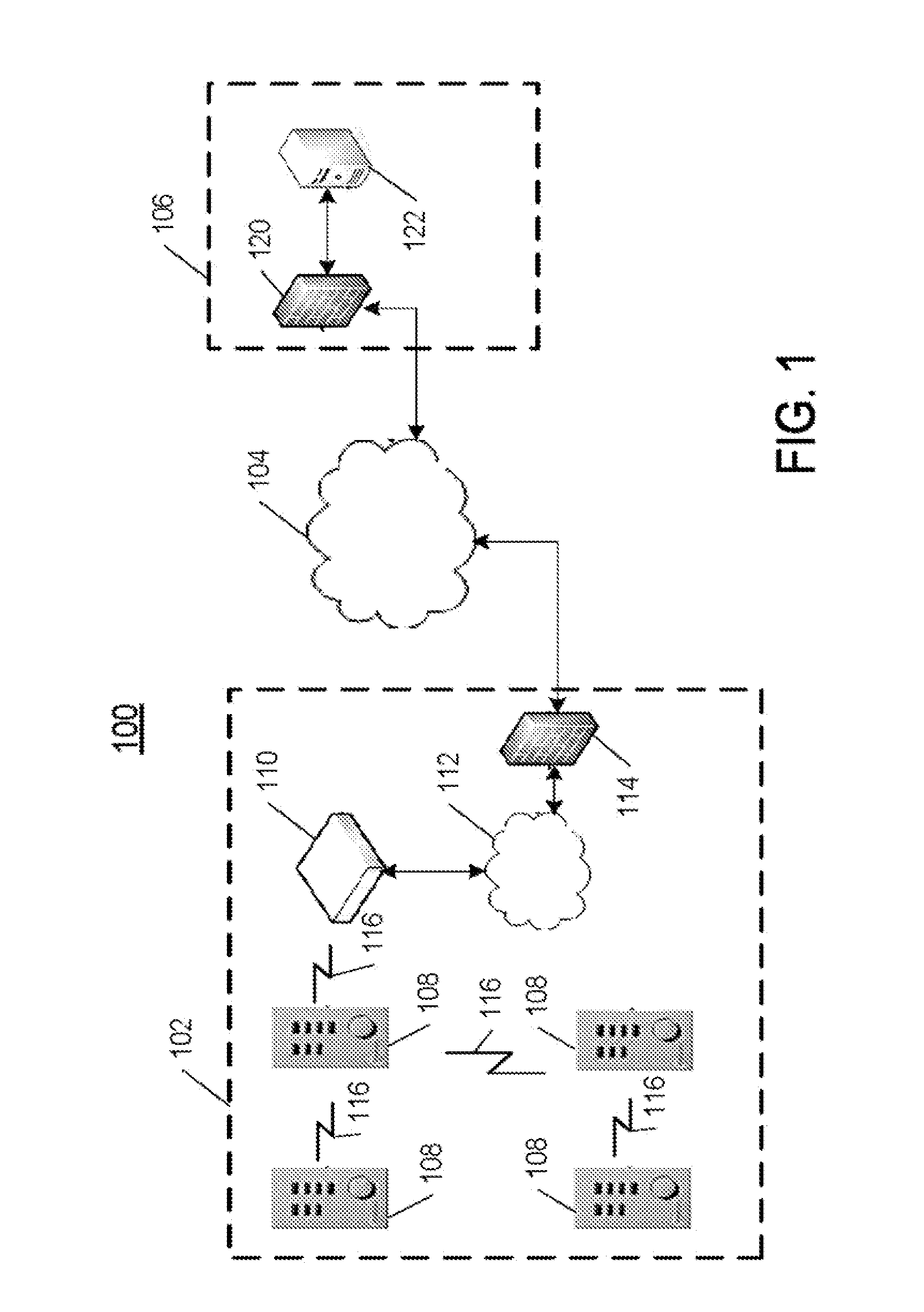
[0016]FIG. 1 is a diagram illustrating an example lighting control system configured in accordance with one example embodiment;

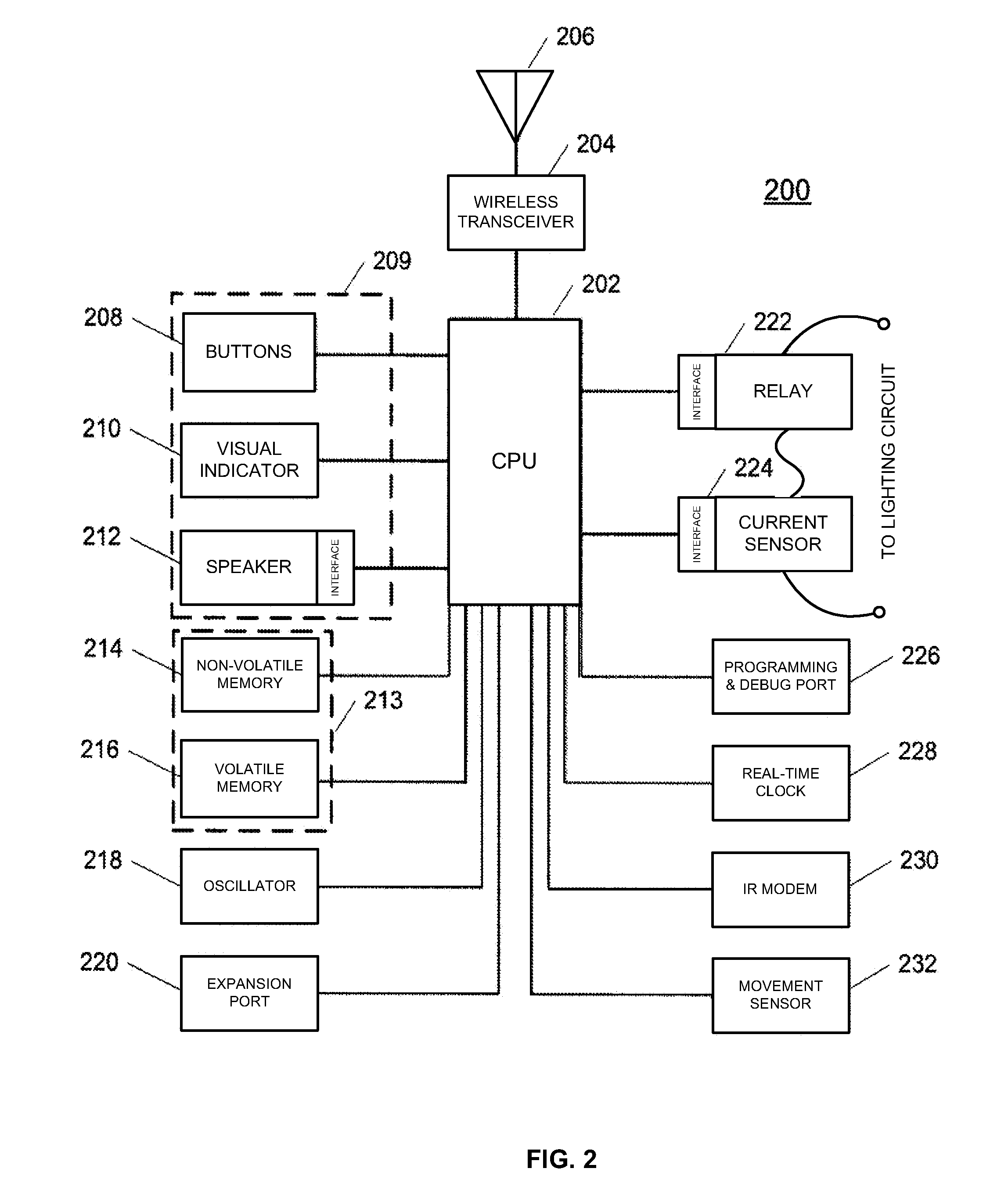
[0017]FIG. 2 is a diagram illustrating an example embodiment of an intelligent switch that can be included in the system of FIG. 1 in accordance with one embodiment;

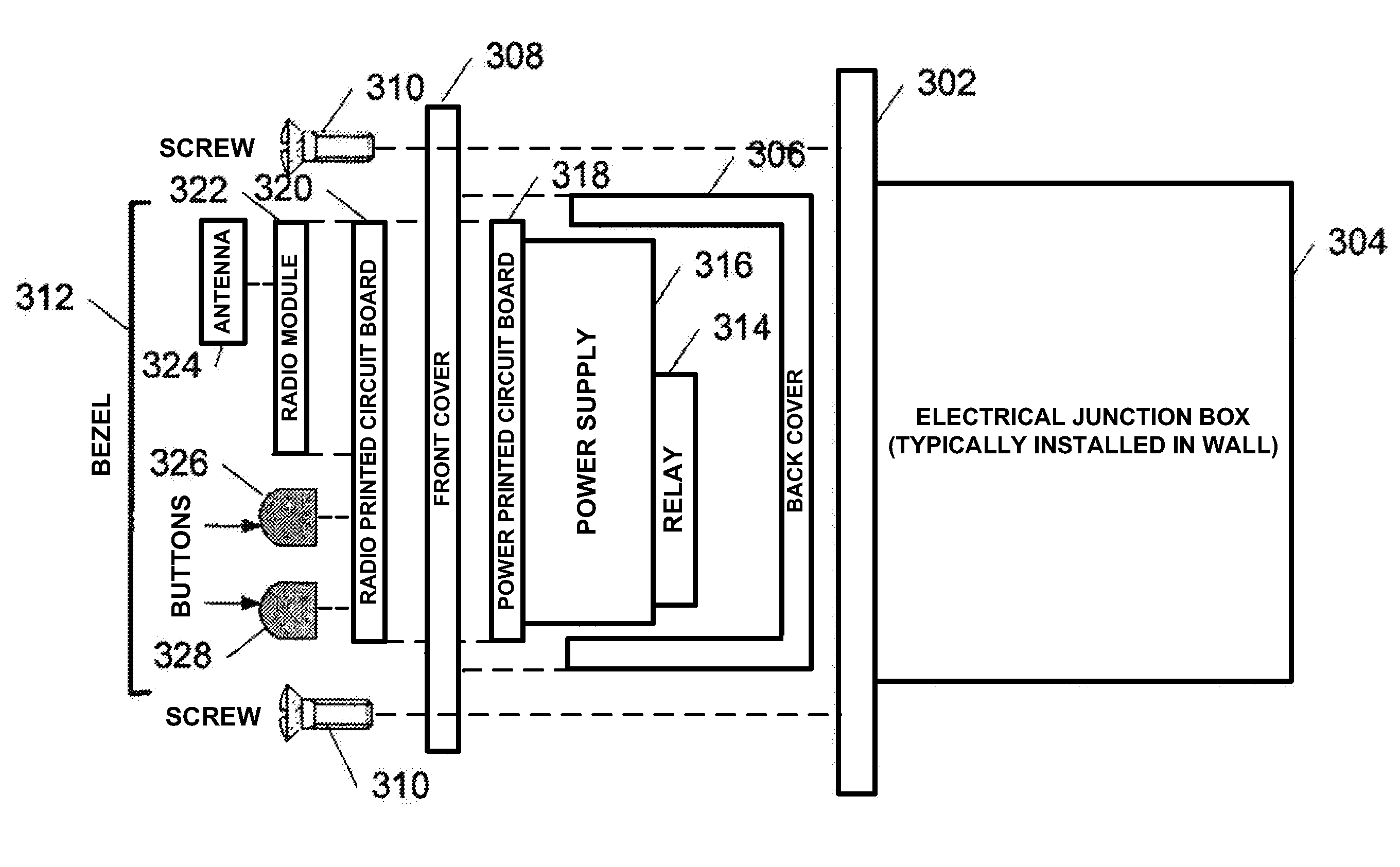
[0018]FIG. 3 is a diagram illustrating installation of the components comprising the switch of FIG. 2 into a standard electrical junction box, such as that used with standard light switch;

[0019]FIG. 4 is a flowchart illustrating an example process for updating the firmware in the switch of FIG. 2 in accordance with one embodiment; and

[0020]FIG. 5 is a flowchart illustrating an example process for detecting burnt-out lamps in the system of FIG. 1 using the switch of FIG. 2 according to one embodiment.

DETAILED DESCRIPTION

[0021]The systems and methods describe...


PUM


Abstract

A lighting control system comprising a plurality of intelligent switches designed to replace a conventional light switch, each of the intelligent switches including a receiver configured to receive communication signals that include rules based instructions for controlling one or more lighting circuits; a circuit interrupter configured to control the amount of current flowing to a lighting circuit; a memory configured to store the rules based instructions; and a processor coupled with the receiver, memory, and circuit interrupter, the processor configured to control the operation of the circuit interrupter based on the rules based instructions stored in memory.

Description

RELATED APPLICATIONS INFORMATION[0001]This application claims priority under 35 U.S.C. 119(e) to U.S. Provisional Application Ser. No. 61 / 131,536, filed Jun. 10, 2008 and entitled “Wireless Lighting Control System,” which is incorporated herein by reference in its entirety.BACKGROUND[0002]1. Technical Field[0003]The embodiments described herein are directed to systems and methods for automated lighting control, and more particularly to rules based, automated lighting control that uses wireless networks to propagate and implement rules based control of lighting systems.[0004]2. Related Art[0005]In, e.g., commercial buildings, lights are often left on after hours, or when no one is in a particular room. This practice waste electricity and causes premature bulb burn out, both of which lead to increased operating costs, as well as a host of other negative effects. Central control systems have been proposed an implemented that attempt to automate lighting control in order to mitigate thi...

Claims


Application Information

Patent Timeline
IPC IPC(8): G05F1/00H05B39/06H05B37/02
CPCH05B37/0245H05B37/02Y02B20/48H05B37/029H05B47/155H05B47/165H05B47/175Y02B20/40
Inventor SMITH, DEREK MATTHEW
Owner GOOGLE LLC
Why Eureka
Try Eureka