
Electrical power distribution and control system and method for remotely controlling power delivery through IP addressable electrical power supply equipment and scanning a network for power control devices

a technology of electrical power distribution and control system, which is applied in the direction of process and machine control, data switching network, instruments, etc., can solve the problems of disparate and incompatible control interfaces, waste of massive amounts of valuable energy, etc., and achieve the effect of reducing electrical consumption

Inactive Publication Date: 2012-12-13
DANIEL REGINALD
View PDF15 Cites 13 Cited by
  • Summary
  • Abstract
  • Description
  • Claims
  • Application Information

AI Technical Summary

Benefits of technology

[0011]The controller provides control options to the user who can selectively enable selected circuit breakers or power strips on a schedule selected by the user. The controller is programmed to control a plurality of identified User Devices such as televisions or other solid-state or computer controlled instruments or appliances, which typically consume power even when in “standby” mode and not in use. The User Devices will be selectively connected to the mains supply only when selectively enabled by Controller inputs, thereby saving valuable energy because the User Devices will not consume any power when not enabled.
[0014]The system of the present invention can reduce electrical consumption by creating a single point of intersection and control to achieve savings of between 10 and 25 percent of total electrical consumption.

Problems solved by technology

All of these devices, taken together, waste massive amounts of valuable energy.
There are also several makers for Internet Protocol (“IP”) addressable power strips, but these devices have disparate and incompatible control interfaces.

Method used


Image

  • Electrical power distribution and control system and method for remotely controlling power delivery through IP addressable electrical power supply equipment and scanning a network for power control devices
  • Electrical power distribution and control system and method for remotely controlling power delivery through IP addressable electrical power supply equipment and scanning a network for power control devices
  • Electrical power distribution and control system and method for remotely controlling power delivery through IP addressable electrical power supply equipment and scanning a network for power control devices

Examples


Embodiment Construction

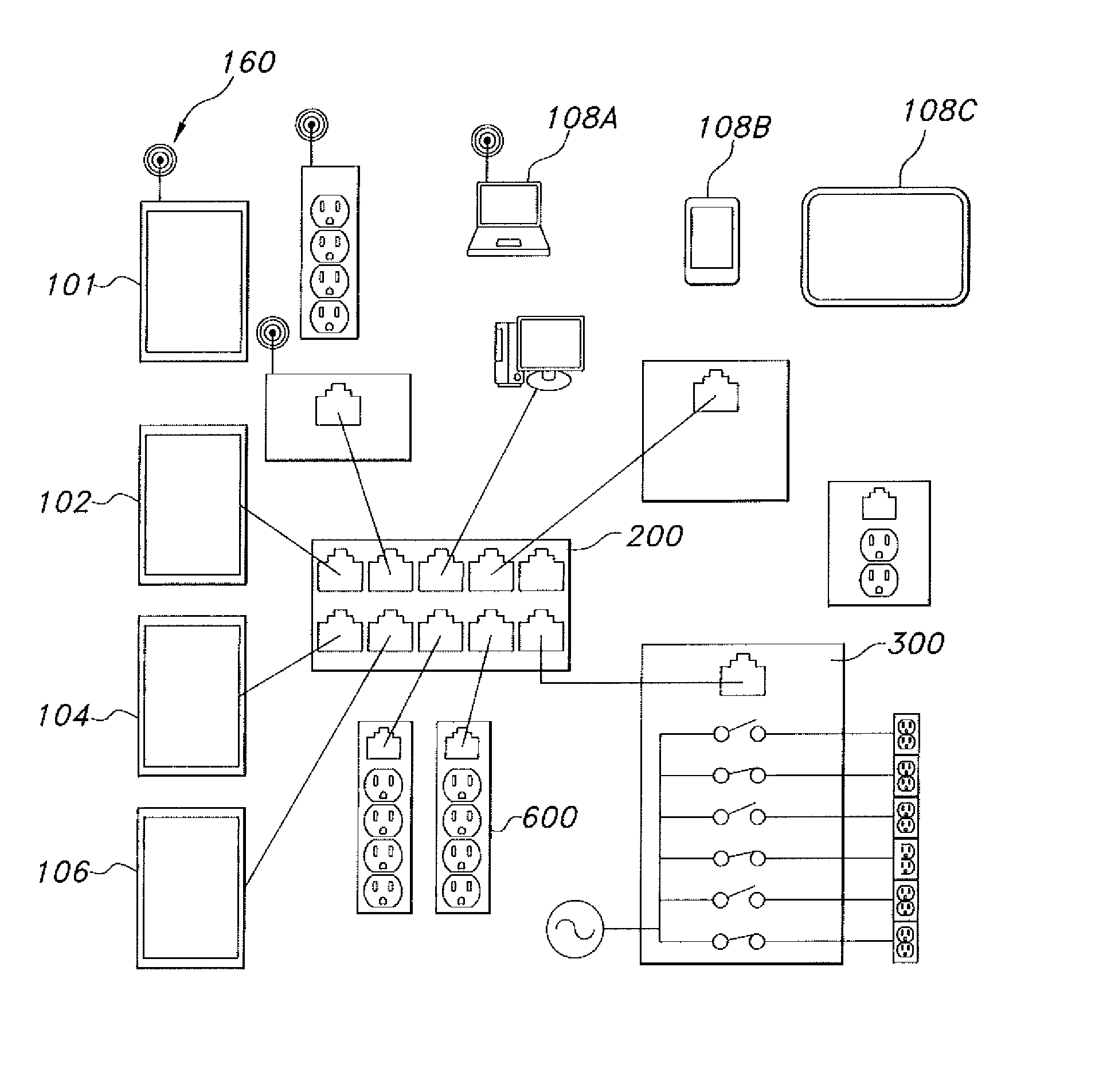
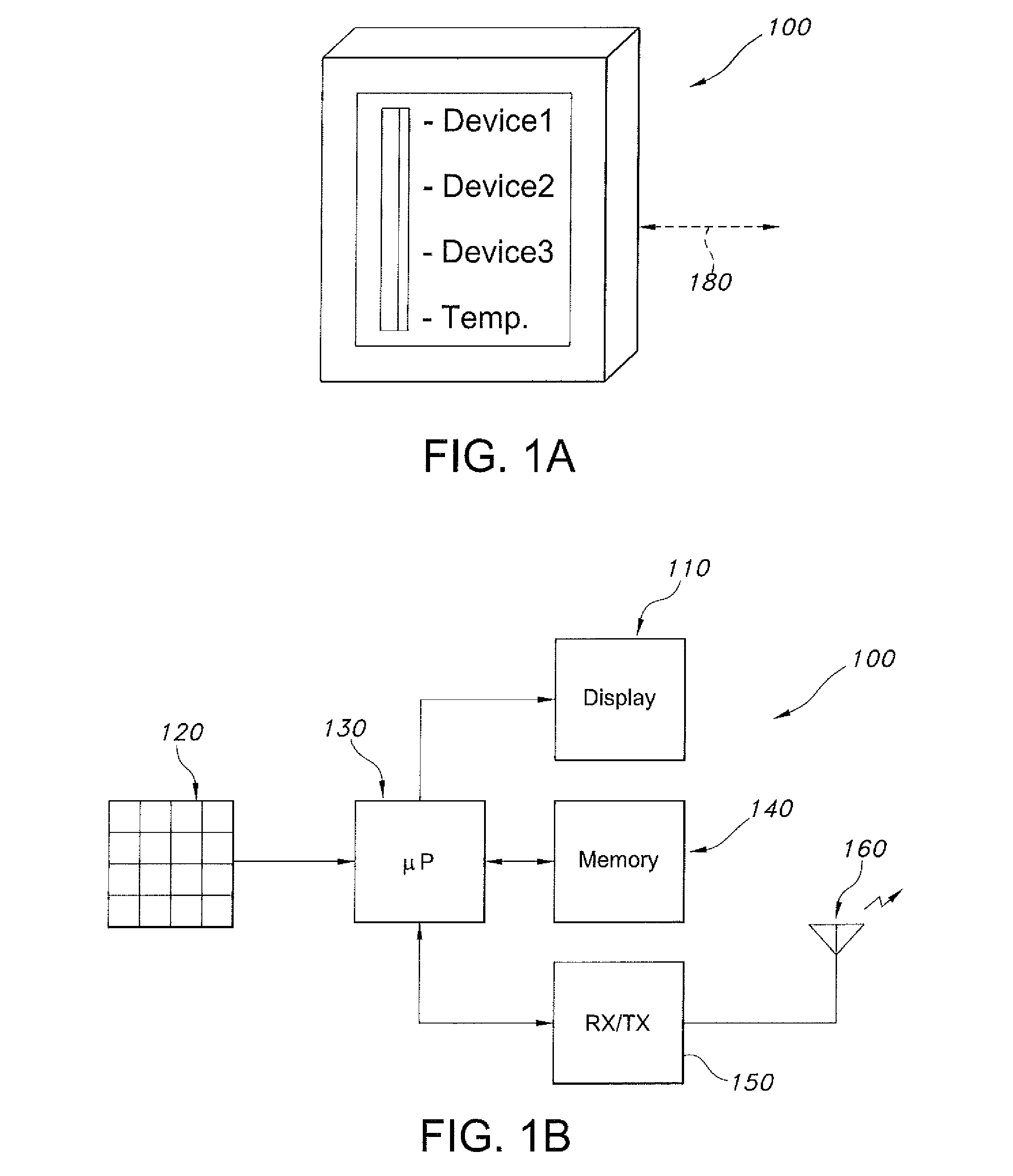
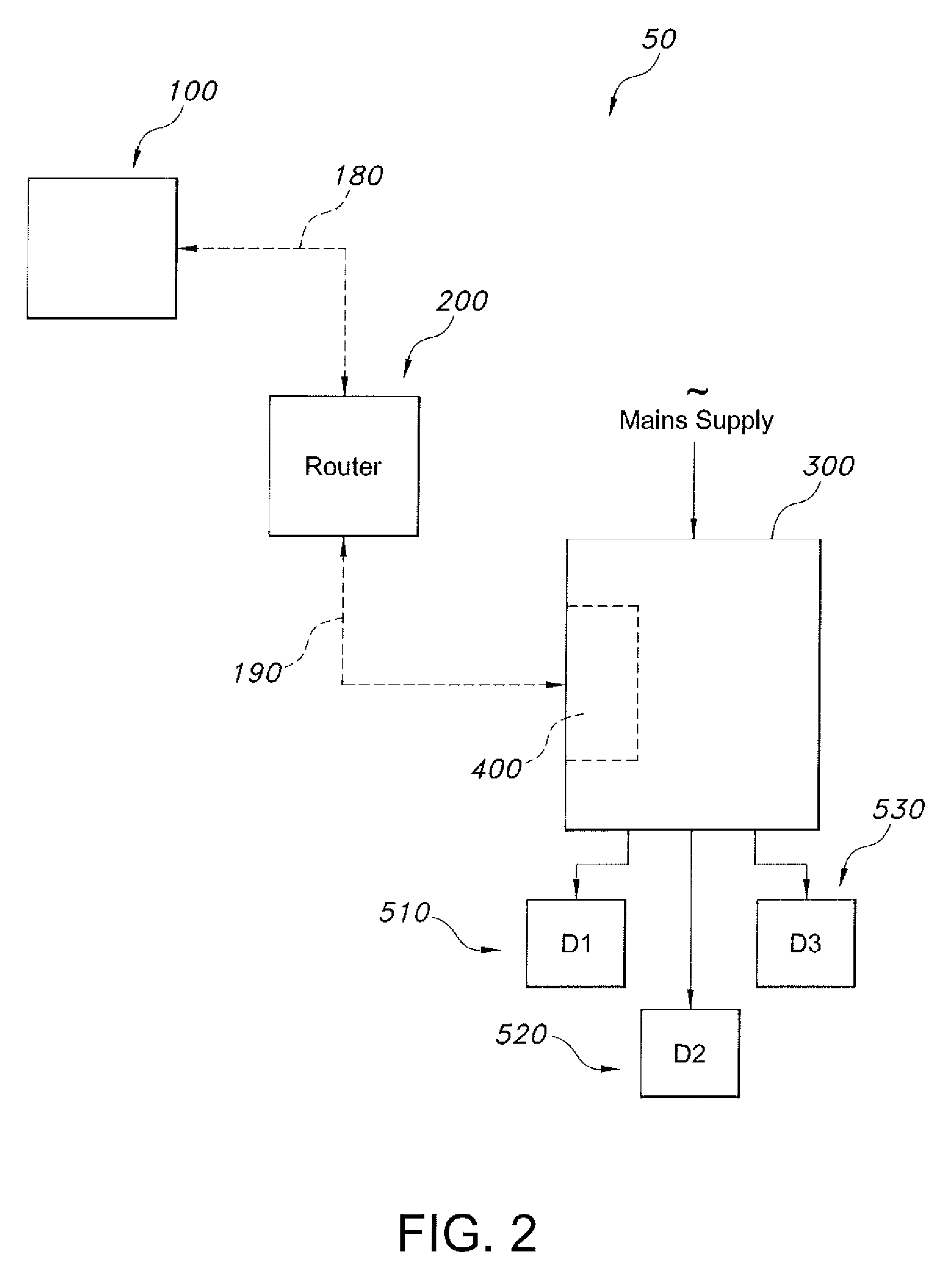
[0024]Turning now to FIGS. 1-8, the system 50 of the present invention has a first user interface and controller 100 which provides control options to the user who can selectively enable selected circuit breakers or power strips on a schedule selected by the user. First user interface and controller 100 preferably includes a wall mountable transportable housing enclosing a microprocessor 130 connected to and responsive to a keyboard or touchscreen input sensor array 120 and a Display 110. First user interface controller's microprocessor 130 is configured with a program storage memory 140 and a digital data telemetry transceiver circuit 150 which is preferably connected with an antenna 160. First user interface and controller 100 is programmed to control a plurality of identified User Devices (e.g., 510, 520, and 530) such as televisions or other solid-state or computer controlled instruments or appliances, which typically consume power even when in “standby” mode and not in use. The...


PUM


Abstract

A power distribution and control system has a wall mounted controller or a transportable controller (e.g., a Smart Phone or wireless Tablet) configured to resemble a solid-state household thermostat having a touchscreen display. The user interface controller provides control options to the user who can selectively enable selected circuit breakers or power strips on a schedule selected by the user. The controller is programmed to control a plurality of identified User Devices such as televisions or other solid-state or computer controlled instruments or appliances, which typically consume power even when in “standby” mode and not in use. The User Devices will be selectively connected to the mains supply only when selectively enabled by Controller inputs, thereby saving valuable energy because the User Devices will not consume any power when not enabled.

Description

PRIORITY CLAIMS AND CROSS-REFERENCE TO RELATED APPLICATIONS[0001]This application claims priority to and is related to commonly owned and co-pending: (1) U.S. provisional patent application No. 61 / 493,931 filed Jun. 6, 2011, and (2) U.S. provisional patent application No. 61 / 505,247, filed Jul. 7, 2011, the entire disclosures of which are incorporated herein by reference.BACKGROUND OF THE INVENTION[0002]1. Field of the Invention[0003]The present invention relates to systems and methods for controlling electric power supplied to solid state devices which typically consume power when not in use and in a “standby” mode.[0004]2. Discussion of the Prior Art[0005]Energy and specifically electrical energy is a commodity that is becoming more and more scarce by the day and yet many user and consumers allow electronic and electrical devices to consume this valuable resource while not in use.[0006]Many solid state devices which consume power, even when not in use (e.g., when in a “standby” mo...

Claims


Application Information

Patent Timeline
Patent Type & Authority Applications(United States)
IPC IPC(8): G06F1/26
CPCG06F1/266G06F1/3287Y02B60/1282H04L12/413H04L12/12Y02D10/00
Inventor DANIEL, REGINALD
Owner DANIEL REGINALD
Learn More