Measuring casing attenuation coefficient for electro-magnetics measurements

a technology of attenuation coefficient and measuring casing, which is applied in the field of measuring casing attenuation coefficient for electromagnetic measurements, can solve problems such as the problem of more problematic data interpretation

Inactive Publication Date: 2009-12-10
SCHLUMBERGER TECH CORP
View PDF12 Cites 29 Cited by
  • Summary
  • Abstract
  • Description
  • Claims
  • Application Information

AI Technical Summary

Benefits of technology

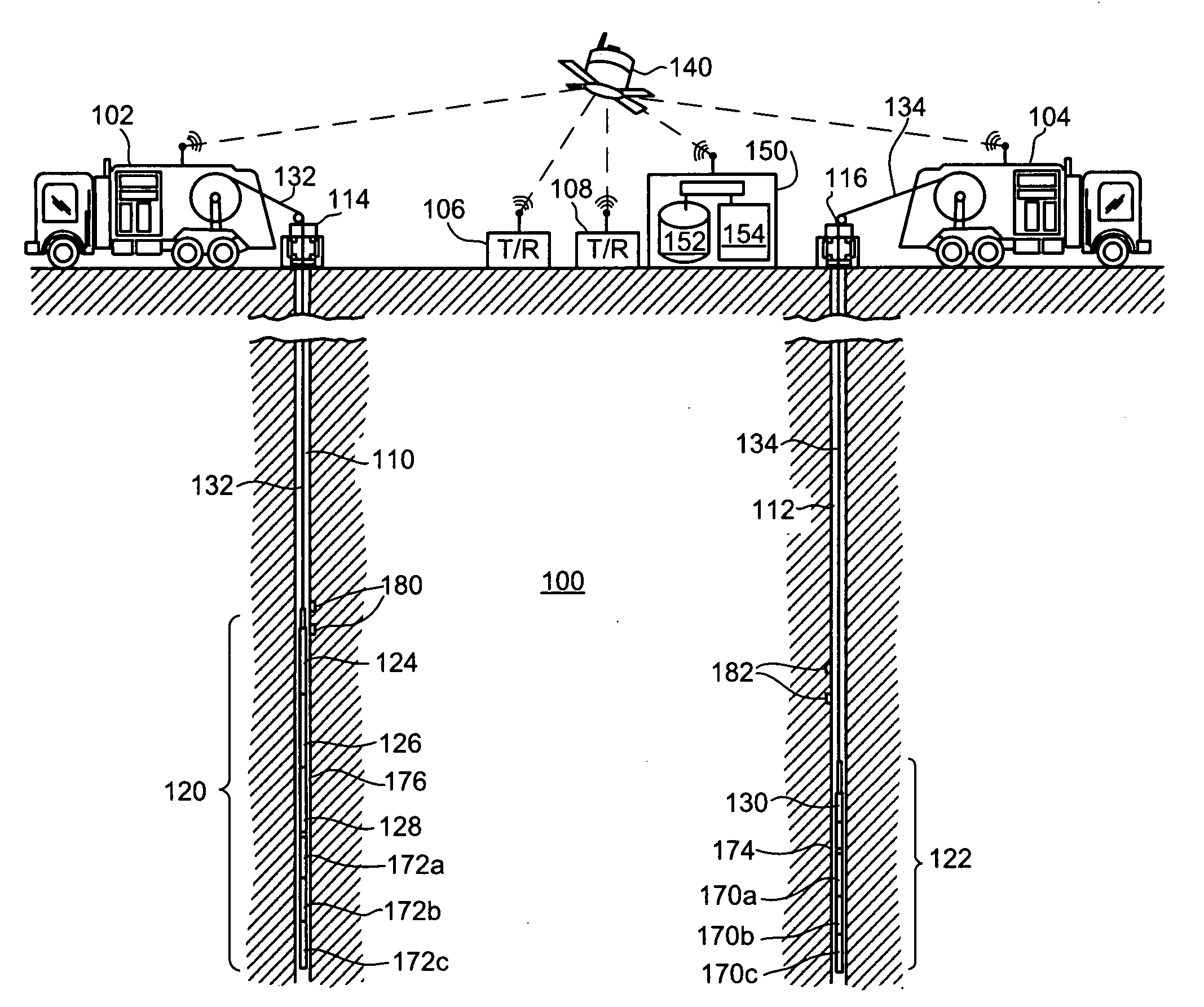
[0011]According to embodiments, a method is provided for making an electromagnetic survey of a formation surrounding a borehole having a casing. The method includes receiving electromagnetic survey measurements of the formation, the measurements being made with an electromagnetic transducer deployed into a section of the borehole that is cased with a conductive casing. Depth correlated casing property data is received that represents one or more properties relating to the casing for the section of the borehole. The casing property data is measured using one or more other transducers. Attenuation in the electromagnetic survey measurements due to the conductive casing is compensated for. The compensation based at least in part on the received casing property data. As used here the term “transducer” means any device that converts one type of energy or physical attribute to another for various purposes including measurement or information transfer. The depth correlated casing property data preferably allows for a derivation of casing thickness, casing conductivity, and / or relative magnetic permeability. The casing property data is preferably measured using one or more downhole tools selected such as cased hole formation resistivity tools, and electromagnetic imaging tools. As used herein, the term “transducer” thus includes sensors and / or receivers as well as transmitters. As used herein the term “attenuation” includes both amplitude attenuation and / or phase shift.

Problems solved by technology

Induction methods employing these systems do work well in open or fiberglass-cased wells, but when the well is steel cased, interpretation of the data becomes more problematic.
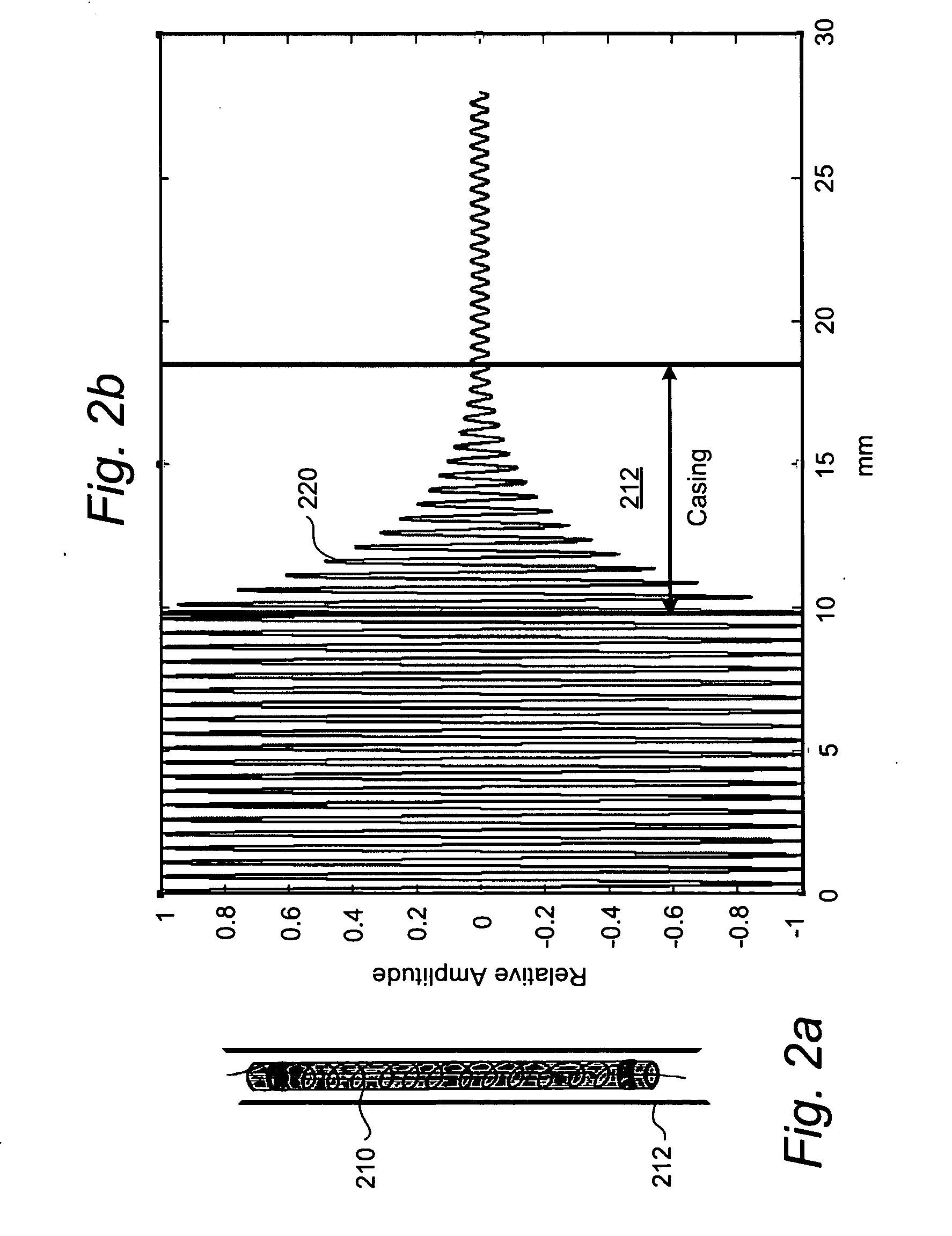
This is due to the fact that the metal casing attenuates the signal and the casing imprint is not uniform as the casing properties (magnetic permeability, conductivity and thickness) are heterogeneous.

Method used


Image

  • Measuring casing attenuation coefficient for electro-magnetics measurements
  • Measuring casing attenuation coefficient for electro-magnetics measurements
  • Measuring casing attenuation coefficient for electro-magnetics measurements

Examples


Embodiment Construction

[0017]In the following detailed description of the preferred embodiments, reference is made to accompanying drawings, which form a part hereof, and within which are shown by way of illustration specific embodiments by which the invention may be practiced. It is to be understood that other embodiments may be utilized and structural changes may be made without departing from the scope of the invention.

[0018]The particulars shown herein are by way of example and for purposes of illustrative discussion of the embodiments of the present invention only and are presented in the cause of providing what is believed to be the most useful and readily understood description of the principles and conceptual aspects of the present invention. In this regard, no attempt is made to show structural details of the present invention in more detail than is necessary for the fundamental understanding of the present invention, the description taken with the drawings making apparent to those skilled in the...


PUM


Abstract

Methods and related systems are described for making an electromagnetic induction survey of a formation surrounding a cased section of a borehole. An electromagnetic transmitter and/or receiver are deployed into the cased section of the borehole. One or more additional devices are used to measure the properties of a conductive casing relating to conductivity, thickness and magnetic permeability. A casing coefficient is then calculated that can then be used for the processing of the deep-sensing induction measurements.

Description

CROSS-REFERENCE TO RELATED APPLICATIONS[0001]This application claims the benefit of U.S. Provisional Application No. 61 / 059,123, entitled “METHOD FOR MEASURING NON-MAGNETIC CASING ATTENUATION COEFFICIENT FOR ELECTROMAGNETIC MEASUREMENTS,” filed Jun. 5, 2008, the disclosure of which is hereby incorporated herein by reference.BACKGROUND OF THE INVENTION[0002]1. Field of the Invention[0003]This patent specification relates to electromagnetic measurements made in connection with boreholes. More particularly, this patent specification relates to methods and systems for correcting for, or determining attenuation due to, a conductive casing of a borehole used in making electromagnetic measurements.[0004]2. Background of the Invention[0005]Electromagnetic measurements are widely used within the oilfield industry to locate fluids inside the reservoir. Connate water is typically much more conductive than the hydrocarbon, and therefore measuring the resistivity of the formation allows clear di...

Claims


Application Information

Patent Timeline
Patent Type & Authority Applications(United States)
IPC IPC(8): G01V3/12
CPCG01V3/30
Inventor LEVESQUE, CYRILLEALUMBAUGH, DAVIDROSTHAL, RICHARDZHANG, HONG
Owner SCHLUMBERGER TECH CORP
Why Eureka
Try Eureka