Solid state image sensor

a solid-state image and sensor technology, applied in the field of solid-state image sensors, can solve the problems of insufficient implementation in some camera systems, ineffectiveness, image degradation, etc., and achieve the effect of suppressing power supply ripples and suppressing image degradation

Active Publication Date: 2009-12-10
PANNOVA SEMIC
View PDF3 Cites 2 Cited by
  • Summary
  • Abstract
  • Description
  • Claims
  • Application Information

AI Technical Summary

Benefits of technology

[0039]According to preferred embodiments of the present invention, by causing a current to be generated at a power supply unit during a horizontal blanking interval (an interval in which a horizontal drive pulse is suspended), i

Problems solved by technology

As shown, in the conventional solid state image sensor, a power supply ripple generated immediately after the start of an effective interval disadvantageously causes image degradation such as shading or ringi

Method used


Image

  • Solid state image sensor
  • Solid state image sensor
  • Solid state image sensor

Examples


first embodiment

[0066]A solid state image sensor according to a first embodiment of the present invention will now be described.

[0067]A solid-state image pickup device included in the solid state image sensor is of an interline transfer type and the configuration thereof is the same as the configuration of the conventional solid-state image pickup device 100 shown in FIG. 20.

[0068]In addition, the configuration of the junction of a vertical register and a horizontal register in the present solid state image sensor is similar to the configuration of the junction of the vertical register and the horizontal register of the conventional solid state image sensor shown in FIG. 22.

[0069]Hereinafter, an example involving a four-phase drive vertical register and a two-phase drive horizontal register will be described. However, it should be noted that the present invention is not limited to a four-phase drive vertical register and a two-phase drive horizontal register.

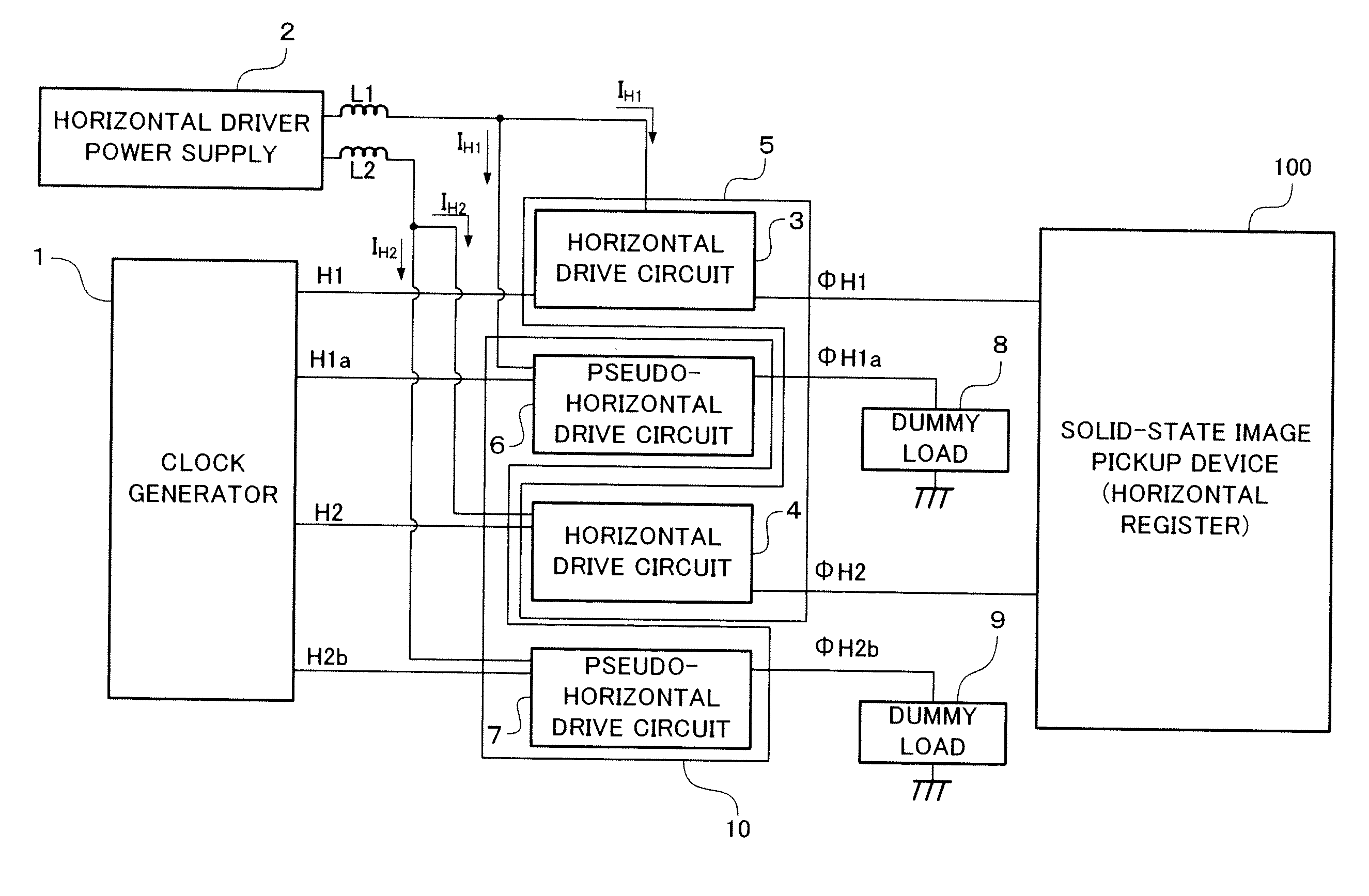
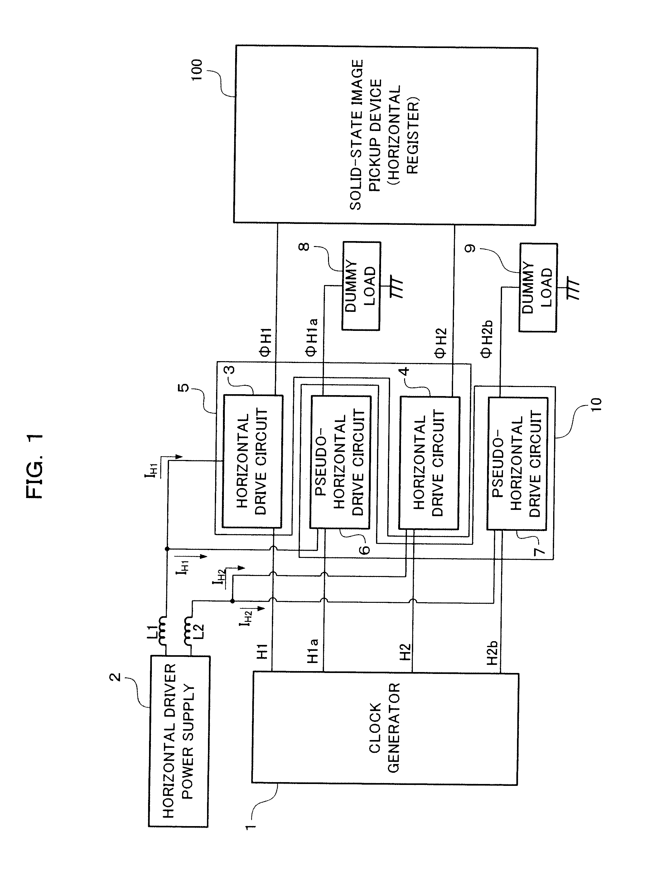
[0070]FIG. 1 is a block diagram partiall...

second embodiment

[0096]A solid state image sensor according to a second embodiment of the present invention will now be described.

[0097]FIG. 4 is a diagram showing an example of the configuration of a solid-state image pickup device included in the solid state image sensor according to the second embodiment of the present invention. The solid-state image pickup device 100 is of an interline transfer type and the configuration thereof is the same as the configuration of the conventional solid-state image pickup device shown in FIG. 20. However, the solid-state image pickup device 100 differs from the conventional device in that a horizontal register 104 is single-phase driven. In other words, in the present second embodiment, the horizontal register 104 is driven solely by a horizontal drive pulse φH1.

[0098]FIG. 5 shows the configuration of the junction of a vertical register and a horizontal register of the solid state image sensor according to the second embodiment of the present invention. As show...

third embodiment

[0120]A solid state image sensor according to a third embodiment of the present invention will now be described.

[0121]A solid-state image pickup device included in the solid state image sensor is of an interline transfer type and the configuration thereof is the same as the configuration of the conventional solid-state image pickup device 100 shown in FIG. 20.

[0122]In addition, the configuration of the junction of a vertical register and a horizontal register in the present solid state image sensor is similar to the configuration of the junction of the vertical register and the horizontal register of the conventional solid state image sensor shown in FIG. 22.

[0123]Hereinafter, an example involving a four-phase drive vertical register and a two-phase drive horizontal register will be described. However, it should be noted that the present invention is not limited to a four-phase drive vertical register and a two-phase drive horizontal register.

[0124]FIG. 9 is a block diagram partiall...


PUM


Abstract

A solid state image sensor capable of preventing image degradation, such as shading and ringing, from occurring in an image portion along the left edge of a screen. The solid state image sensor includes, in addition to a horizontal drive circuit that generates a horizontal drive pulse for driving a horizontal register, a pseudo-horizontal drive circuit that generates a pseudo-horizontal drive pulse successive to the horizontal drive pulse during a horizontal blanking interval. The horizontal drive circuit and pseudo-horizontal drive circuit are connected to a horizontal driver power supply unit, which generates, during the horizontal blanking interval, a current that is equal to a current generated by the horizontal driver power supply unit during an effective interval. This arrangement can prevent any power supply ripples from occurring immediately after the beginning of the effective interval.

Description

TECHNICAL FIELD[0001]The present invention relates to a solid state image sensor to be used in a CCD camera or the like.BACKGROUND ART[0002]A conventional solid state image sensor will now be described with reference to the drawings. FIG. 20 shows an example of the configuration of a conventional interline transfer solid-state image pickup device.[0003]As shown in FIG. 20, a solid-state image pickup device 100 includes, on a substrate, photodiodes (light receiving units) 101, readout gates 102, vertical registers 103, a horizontal register 104, and a floating diffusion layer charge detecting unit 105.[0004]The two-dimensionally arranged photodiodes 101 photoelectrically convert incident light and accumulate a signal charge whose amount corresponds to the amount of incident light. The readout gates 102 read out the signal charge accumulated in the photodiodes 101 to the vertical registers 103. The vertical registers 103 transfer the signal charge received from the photodiodes 101 via...

Claims


Application Information

Patent Timeline
IPC IPC(8): H04N5/335H04N5/365H04N5/372
CPCH01L27/14812H04N5/372H04N5/3658H01L27/14843H04N25/677H04N25/71
Inventor ORIHARA, KOZOTAKEMORI, SHUNJIROKOHNO, AKIYOSHI
Owner PANNOVA SEMIC
Why Eureka
Try Eureka