Telescope

a technology of telescopic beams and beams, applied in the field of telescopic beams, can solve the problems of high production cost, mechanically complicated cardanic beams, dither compensation, etc., and achieve the effect of being produced at a lower cost and being robust in us

Inactive Publication Date: 2009-12-10
CARL ZEISS SPORTS OPTICS +1
View PDF11 Cites 7 Cited by
  • Summary
  • Abstract
  • Description
  • Claims
  • Application Information

AI Technical Summary

Benefits of technology

[0006]It is an object of the invention to develop further a telescope of the type mentioned at the beginning to the effect that the above-mentioned disadvantages are avoided. In particular, the aim is to be able to implement a dither compensation in a telescope which can be produced at lower cost and is simultaneously robust in use.

Problems solved by technology

The problem of dither compensation arises chiefly in the case of telescopes of long focal length.
Known telescopes use mechanically complicated cardanic bearings which are associated with high production costs.
Moreover, these telescopes are frequently sensitive to shock loads.

Method used


Image

  • Telescope
  • Telescope
  • Telescope

Examples


Embodiment Construction

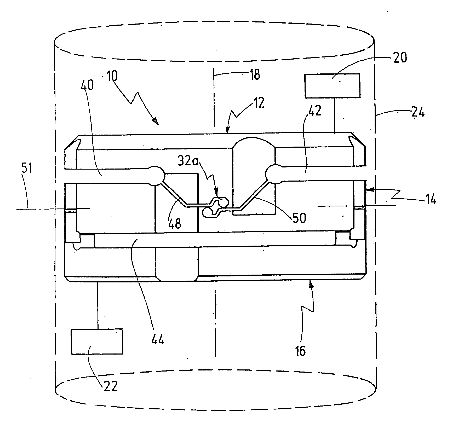
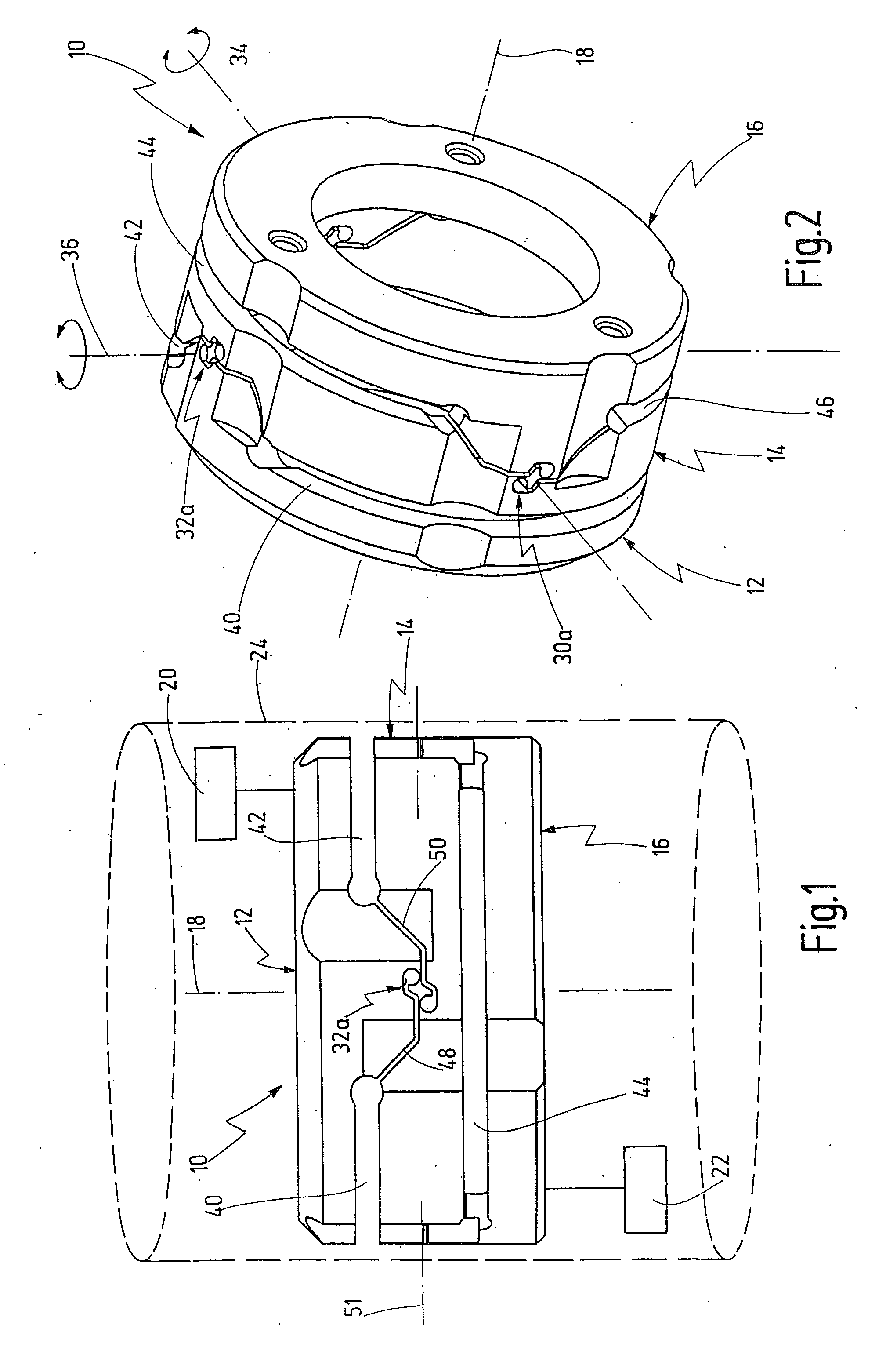
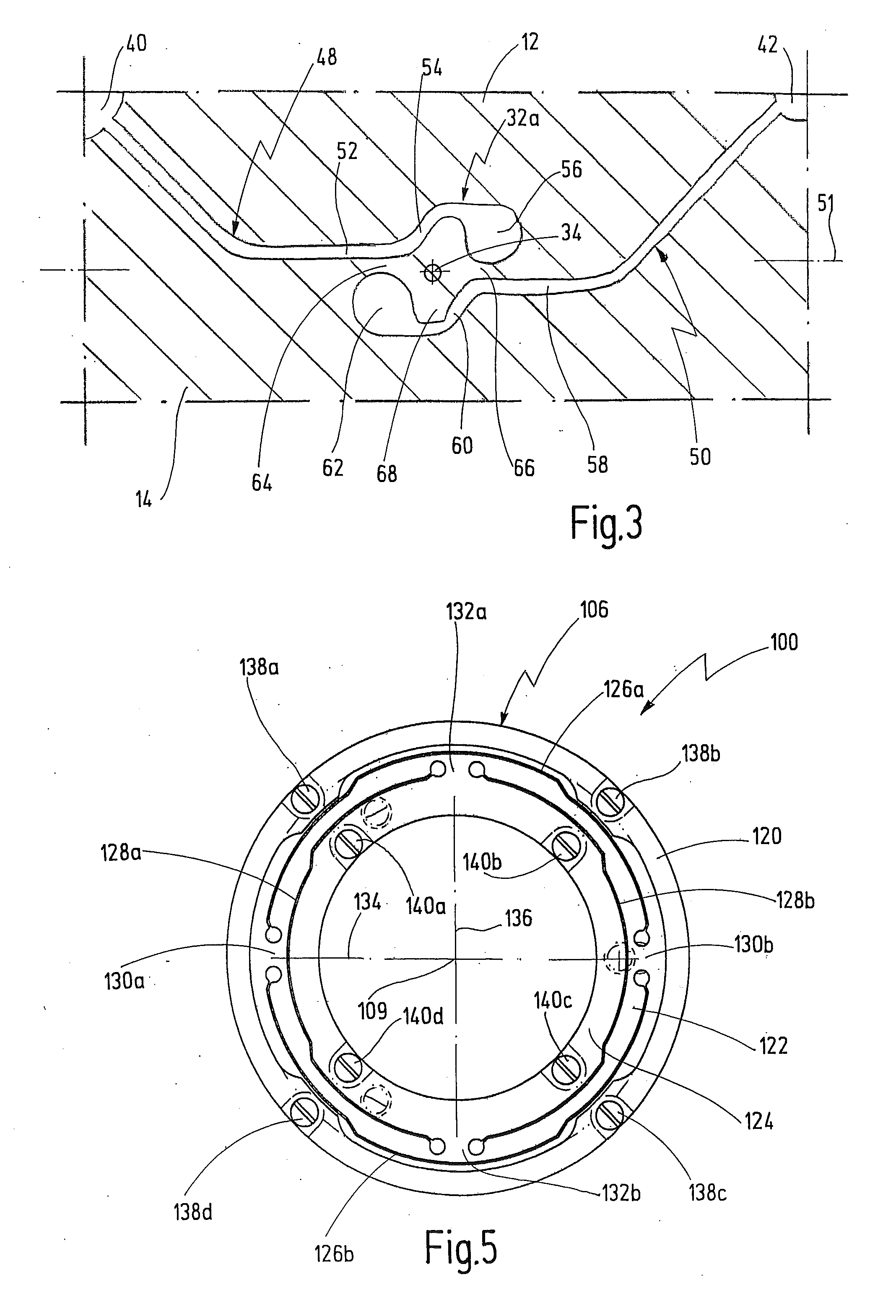
[0063]The invention relates to joints which are used in an optical device, in particular in a telescope, for elastic suspension of an optical assembly. The assembly, in particular an inverting system in a telescope, is intended to be stabilized by the suspension against dither motions in space. This preferably happens passively through the application of the necessary stabilization forces solely by the inertial forces of the mass of the assembly.

[0064]The joints are designed as cardanic spring joints. They have two joint axes which run perpendicular to one another, are defined by in each case two spring joint sites, and respectively permit a rotation by, for example, approximately ±5°. The joint axes in this case define a plane and intersect at a central point which lies on the axis of the substantially cylindrical joints. The spring joint sites are preferably equally removed from the central point.

[0065]FIGS. 1 to 3 show a first exemplary embodiment of a joint 10 according to the i...


PUM


Abstract

A telescope has a joint for universally bearing an optical assembly in relation to a housing. The joint is designed as an elastic spring joint.

Description

CROSS REFERENCE TO RELATED APPLICATION[0001]The present application claims priority of German patent application No. 10 2008 026 978.6 filed on May 29, 2008.BACKGROUND OF THE INVENTION[0002]The invention generally relates to telescopes.[0003]More specifically, the invention relates to a telescope having a joint for universally bearing an optical assembly in relation to a housing.[0004]Telescopes of the above-mentioned type are generally known. The cardanic bearing of the assembly, usually of the inverting system of the telescope, serves the purpose of compensating dither motions which are transmitted by the user to the telescope. The problem of dither compensation arises chiefly in the case of telescopes of long focal length.[0005]Known telescopes use mechanically complicated cardanic bearings which are associated with high production costs. Moreover, these telescopes are frequently sensitive to shock loads.SUMMARY OF THE INVENTION[0006]It is an object of the invention to develop fu...

Claims


Application Information

Patent Timeline
Patent Type & Authority Applications(United States)
IPC IPC(8): G02B23/16F16D1/00
CPCG02B23/00Y10T403/606G02B27/646
Inventor DOBERMANN, DIRKRINK, DIETERROBOTTA, RAINERBECKER, KURTGUENTHER, GEORGHOFMANN, JENS
Owner CARL ZEISS SPORTS OPTICS
Why Eureka
Try Eureka