
Scalable bandwidth system, radio base station apparatus and radio terminal apparatus

a bandwidth system and radio base station technology, applied in the direction of wireless communication, signalling characterisation, wireless communication, etc., can solve the problem of likely unbalanced traffic in the frequency domain, and achieve the effect of reducing unbalanced traffic and maximum bandwidth

Inactive Publication Date: 2009-12-10
PANASONIC CORP
View PDF16 Cites 56 Cited by
  • Summary
  • Abstract
  • Description
  • Claims
  • Application Information

AI Technical Summary

Benefits of technology

"The present invention is a scalable bandwidth system, wireless base station apparatus, and wireless terminal apparatus that can reduce unbalance in traffic in the maximum bandwidth. This is achieved by assigning flexibly bandwidths to each terminal based on its bandwidth capability, allowing for efficient use of available bandwidth. The invention takes into account the bandwidth capabilities of each terminal in a cell, and the unbalance in traffic in the maximum bandwidth can be reduced by transmitting a synchronization signal and reporting information of a plurality of candidate bands unique to a cell of the wireless base station apparatus using a shared channel in the same band as the determined band. Overall, the invention provides a more effective solution for reducing unbalance in traffic and improving the performance of wireless communication networks."

Problems solved by technology

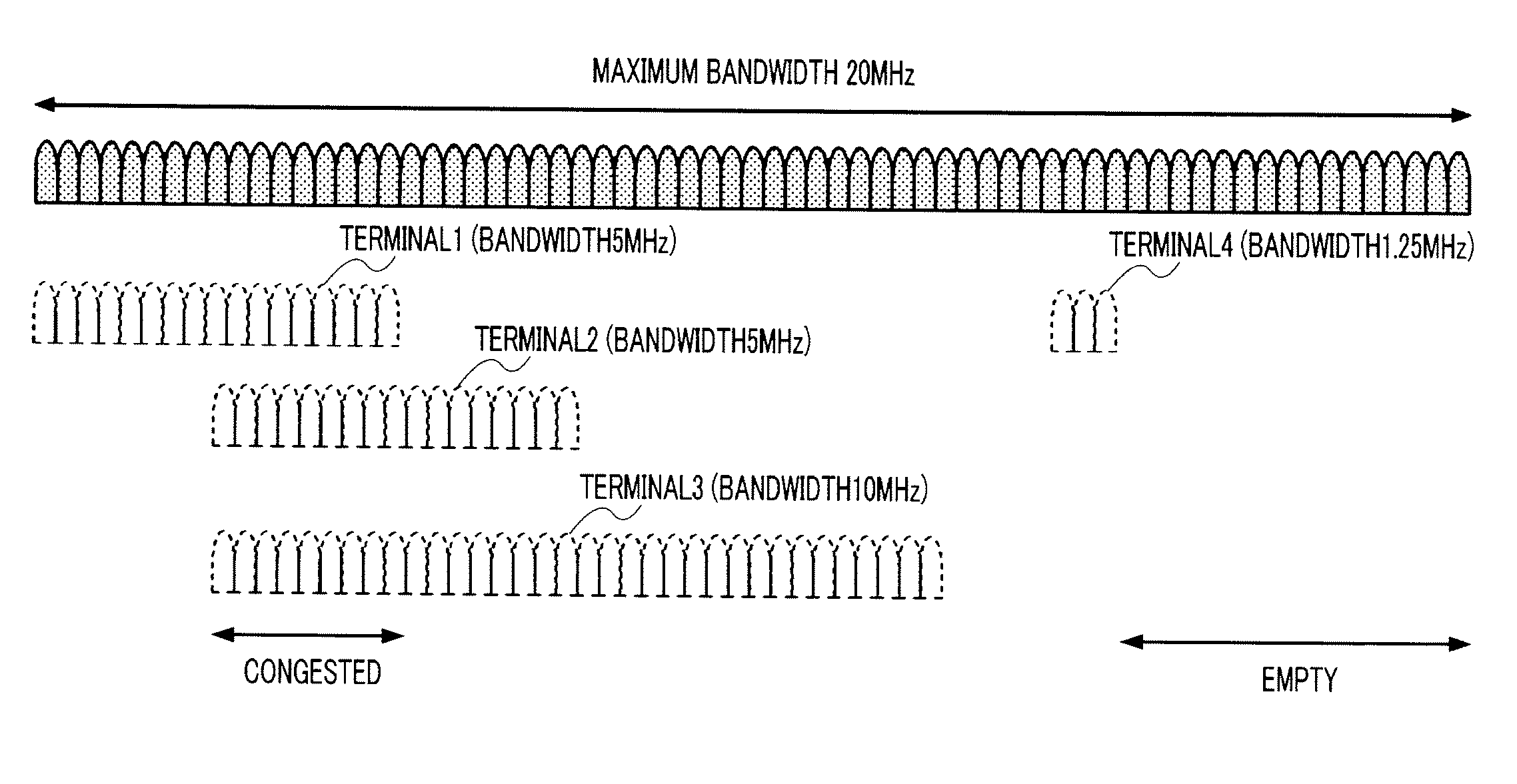
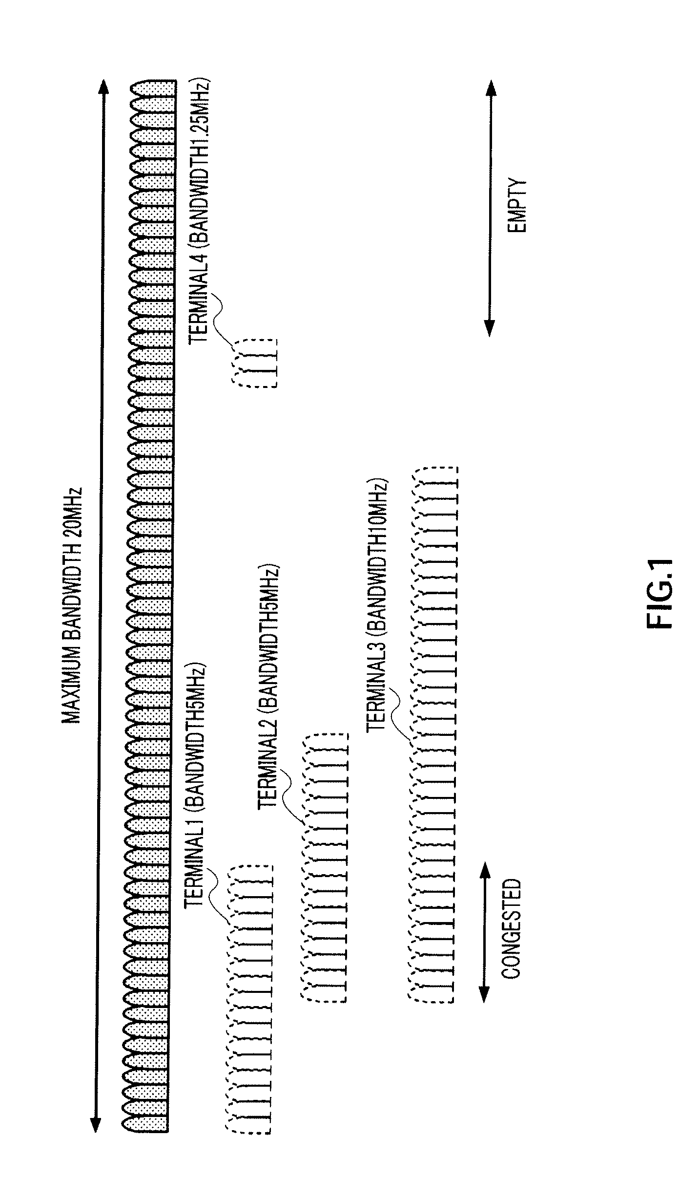
By the way, in this scalable bandwidth system, when each terminal carries out initial cell search such as symbol synchronization using a random frequency band and sets up communication independently, as shown in FIG. 1, traffic in the frequency domain is likely to become unbalanced.

Method used


Image

  • Scalable bandwidth system, radio base station apparatus and radio terminal apparatus
  • Scalable bandwidth system, radio base station apparatus and radio terminal apparatus
  • Scalable bandwidth system, radio base station apparatus and radio terminal apparatus

Examples


embodiment 1

[0032]FIG. 3 shows a configuration of a wireless base station apparatus (hereinafter, a “base station”) used in a scalable bandwidth system of this embodiment and FIG. 4 shows a configuration of a wireless terminal apparatus (hereinafter, a “terminal”) that carries out communication with base station apparatus 100.

[0033]Similar to a base station of a general scalable bandwidth system, base station 100 assigns on a per terminal basis flexibly a bandwidth less than a plurality of the maximum bandwidths supported by the base station as a communication band of each terminal and carries out OFDM communication between the base station and each terminal.

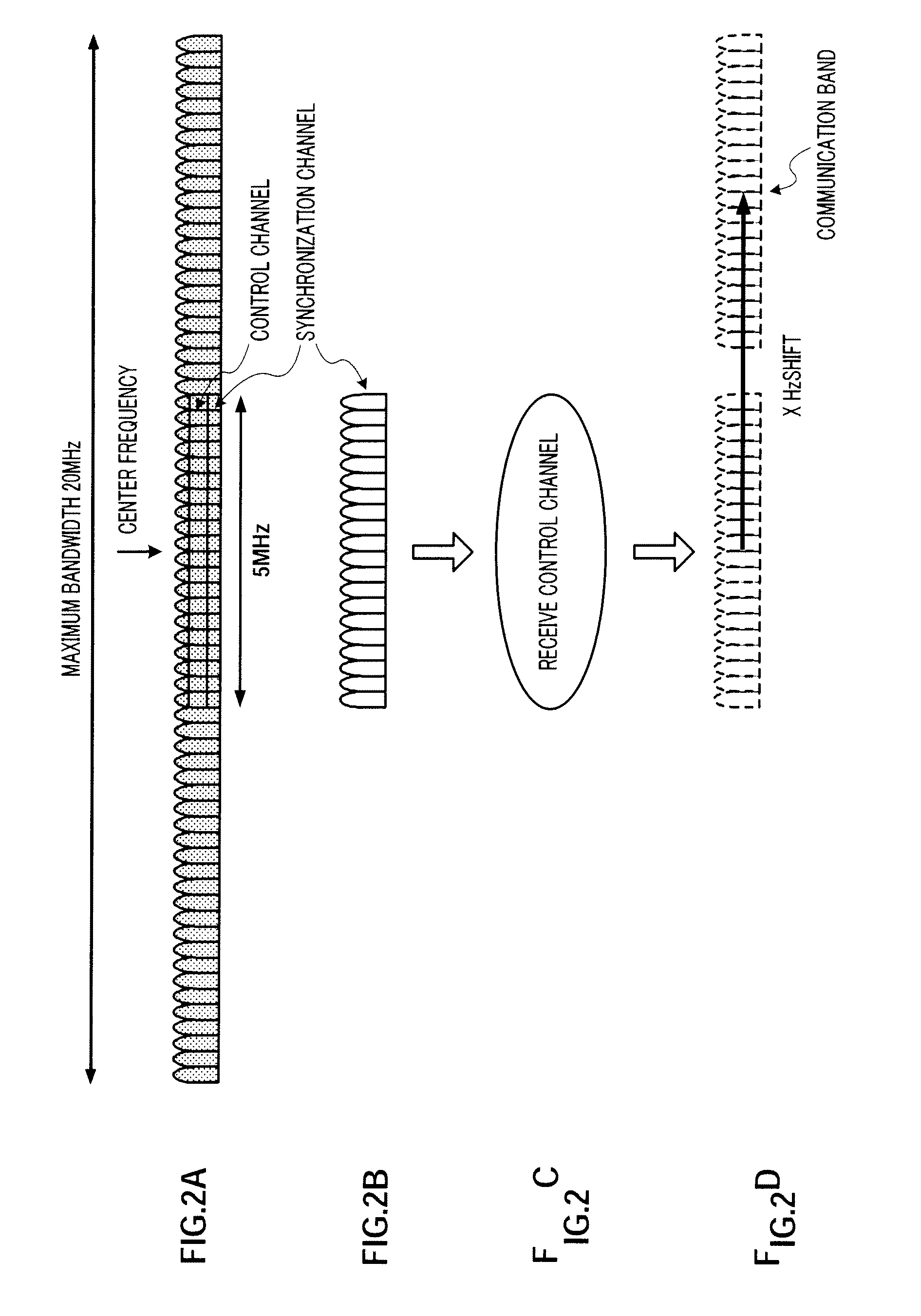
[0034]Further, in this embodiment, base station 100 transmits a synchronization code (synchronization signal) and band assignment information to each terminal from a band (in this embodiment, a band (for example, 5 MHz) of the central portion of the maximum bandwidth) determined in advance in a cell.

[0035]First, the configuration of base st...

embodiment 2

[0056]Embodiment 1 proposes that the terminal reports bandwidth capability of the terminal to the base station, and the base station assigns a communication band of each terminal by referring to bandwidth capability of each terminal and indicates assigned communication band information of each terminal using the shared channel, so that unbalance in traffic is reduced in the maximum bandwidth.

[0057]In contrast with this, Embodiment 2 proposes that a base station indicates candidate band information to each terminal using such as a common channel and a terminal selects a band matching bandwidth capability of the terminal from this candidate band information, so that unbalance in traffic is reduced in the maximum bandwidth.

[0058]FIG. 7 shows a configuration of the base station of this embodiment and the same reference numerals will be assigned to the corresponding parts of FIG. 3. FIG. 8 shows a configuration of a terminal of this embodiment and the same reference numerals will be assi...

embodiment 3

[0070]FIG. 11 shows a configuration of a base station of this embodiment, and the same reference numerals will be assigned to corresponding parts of FIG. 7. Base station 500 has congestion information generating section 502. Congestion information generating section 502 inputs selected band information (UE selected band) selected by each terminal, generates congestion information showing congestion of band assignment in the maximum bandwidth based on selected band information and sends out this information to transmission controlling section 501. Transmission controlling section 501 selectively outputs transmission data 1 to n and congestion information. In this way, base station 300 of FIG. 7 transmits candidate band information, and, on the other hand, the base station of this embodiment transmits congestion information 502.

[0071]FIG. 12 shows a configuration of the terminal of this embodiment, and the same reference numerals will be assigned to the corresponding parts of FIG. 8. ...


PUM


Abstract

A scalable bandwidth system wherein even when various terminals having different bandwidth capabilities are existent in a cell, the unbalance of traffic in the maximum bandwidth can be reduced. Terminals (200) transmit their respective bandwidth capability information. A base station (100) assigns, based on the bandwidth capability information and identification signals transmitted from the terminals (200), communication bands to the respective terminals, and transmits, by use of a shared channel, information of the communication bands assigned to the terminals. In this way, the base station (100) can assign the bands to the terminals with the bandwidth capabilities of the respective terminals in the cell taken into account, whereby the unbalance of traffic in the maximum bandwidth can be reduced.

Description

TECHNICAL FIELD[0001]The present invention relates to, particularly, a scalable bandwidth system, wireless base station and wireless terminal apparatus that carry out multicarrier communication by assigning on a per terminal basis flexibly a bandwidth less than a plurality of maximum bandwidths supported by the wireless base station apparatus as a communication band for each wireless terminal apparatus.BACKGROUND ART[0002]Conventionally, upon carrying out multicarrier communication represented by the OFDM (Orthogonal Frequency Division Multiplexing) scheme, a wireless communication system is proposed for supporting a plurality of maximum bandwidths at the wireless base station (hereinafter, simply a “base station”) and enabling flexible assignment of bandwidths used for actual communication from the maximum bandwidths by each wireless communication terminal (hereinafter, simply a “terminal”). Such a wireless communication system is referred to as a “scalable bandwidth system.”[0003]...

Claims


Application Information

Patent Timeline
Patent Type & Authority Applications(United States)
IPC IPC(8): H04W72/04H04W28/20
CPCH04L1/0025H04L5/023H04L27/2656H04W72/048H04W28/20H04W72/0406H04L27/2662H04W72/20H04W72/51
Inventor NAKA, KATSUYOSHIMATSUO, HIDENORIHAGA, HIROKIXU, MING
Owner PANASONIC CORP
Learn More