
Digital signal transmission and reception

a digital signal and reception technology, applied in the field of digital signal transmission and reception, can solve problems such as imposing pressure on the digital payload carried by each channel

Inactive Publication Date: 2009-12-10
SONY CORP
View PDF9 Cites 27 Cited by
  • Summary
  • Abstract
  • Description
  • Claims
  • Application Information

AI Technical Summary

Benefits of technology

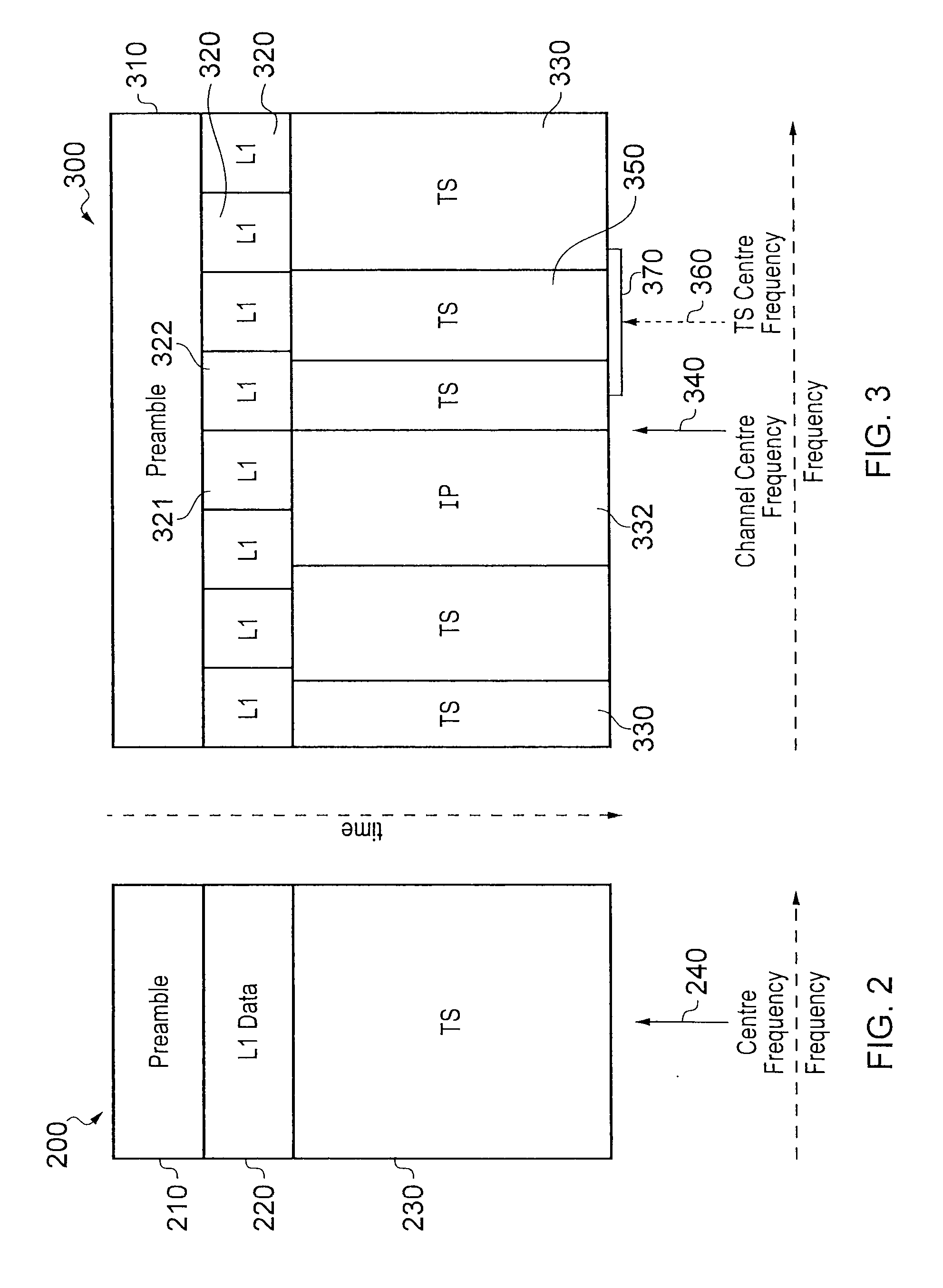
This patent describes a digital signal transmitter that can transmit multiple data streams using different frequency bands. The transmitter includes a mechanism to indicate to a receiver where within a frequency channel it should align its receiver bandwidth in order to receive a desired data stream. The technical effect of this invention is that it allows for efficient use of channels of width greater than the receiver bandwidth or the width of any individual payload stream.

Problems solved by technology

This demand imposes pressure on the digital payload carried by each channel.

Method used


Image

  • Digital signal transmission and reception
  • Digital signal transmission and reception
  • Digital signal transmission and reception

Examples


Embodiment Construction

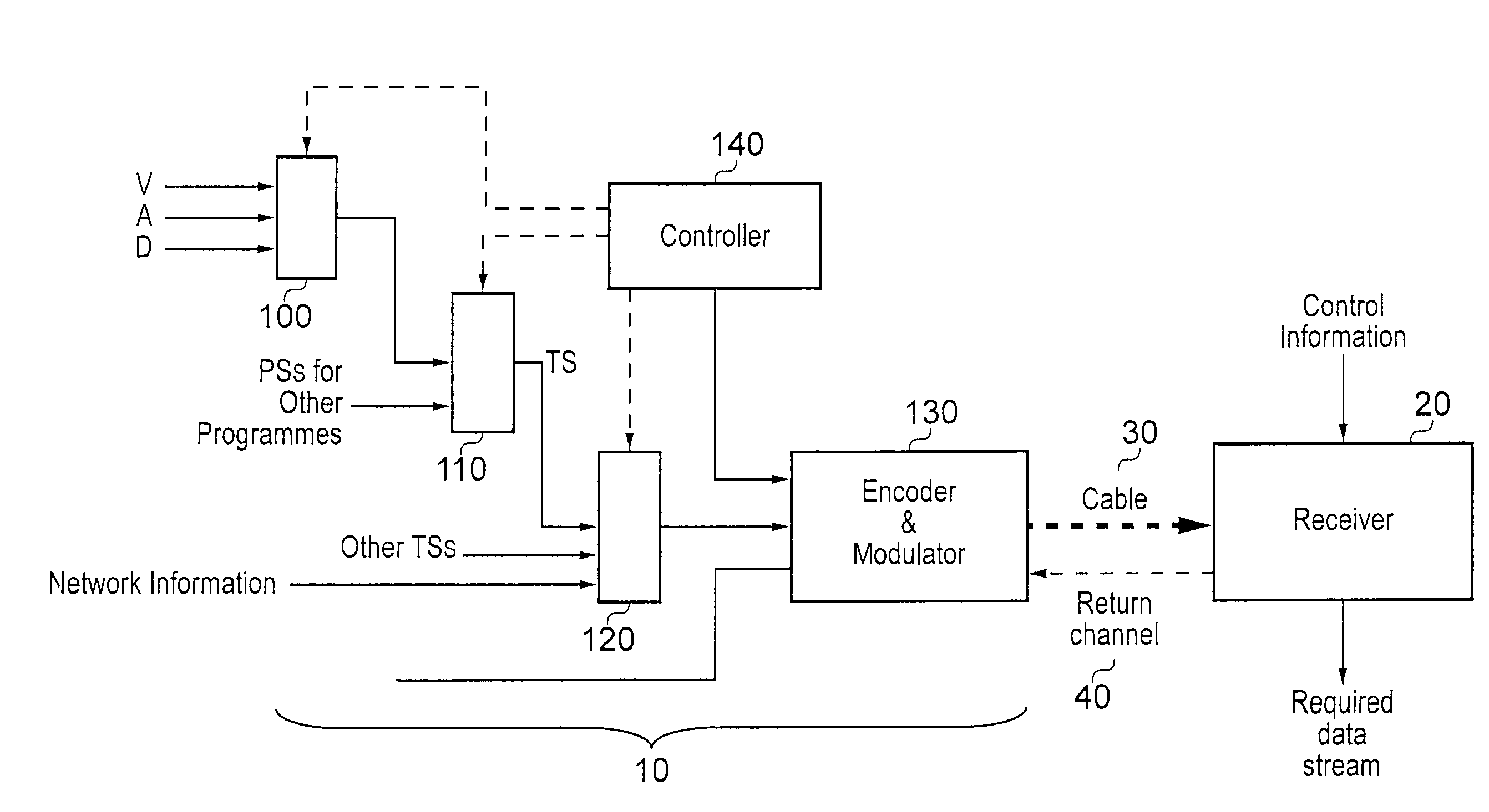
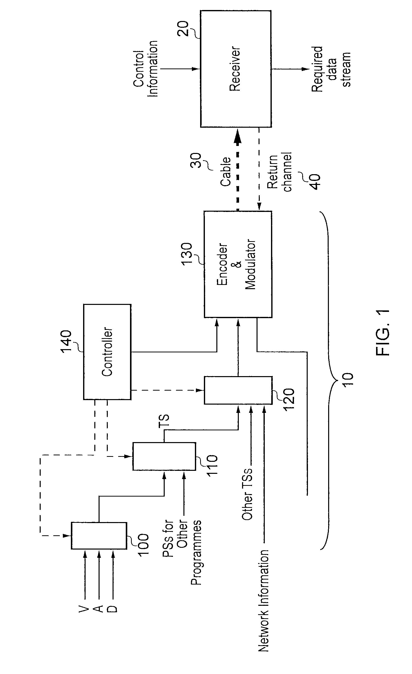
[0021]Referring now to FIG. 1, a digital signal transmission system comprises a transmitter 10 and a receiver 20, linked by a transmission link 30. In this example, the transmission link is a wired link (which term encompasses electrically conductive wires and optical fibres), and the system of FIG. 1 is arranged to provide a cable television service. In general terms, except where differences are described, the apparatus operates in accordance with the DVB-C standards.

[0022]An optional return channel 40, by which data such as purchasing data or viewing statistics can be carried from the receiver to the transmitter, is also provided. The return channel is conventional and will not be described further here.

[0023]The present techniques are not limited to cable systems. Corresponding techniques may be used in other transmission systems such as terrestrial or satellite systems.

[0024]The transmitter comprises a number of programme multiplexers 100, one for each programme data stream to ...


PUM


Abstract

A digital signal transmitter in which multiple data streams are each transmitted by modulation of a respective frequency band within one of a group of frequency channels, the frequency bands each occupying no more than a predetermined maximum bandwidth less than or equal to the channel width; comprises means for transmitting at respective frequency positions within each frequency channel, one or more instances of band information defining the frequency bands corresponding to all of the data streams carried within that frequency channel, the one or more instances being arranged so that any portion of the frequency channel equal in extent to the predetermined maximum bandwidth includes at least one instance of the band information.

Description

FIELD OF THE INVENTION[0001]This invention relates to digital signal transmission and reception.DESCRIPTION OF THE PRIOR ART[0002]Digital signals are transmitted in applications such as digital television broadcasting. Standards such as the so-called DVB standards have existed since the 1990s, and provide a range of quadrature amplitude modulation (QAM) schemes for broadcast services, along with formats for the transmission of accompanying control data and metadata. These standards define both the radio frequency (RF) techniques used to carry the data and the way in which the data representing different broadcast services is organised into packets and streams for transmission.[0003]The DVB standards are described extensively elsewhere, so only a brief summary will now be given, with reference to the standards relating to the transmission of broadcast cable services, although it will of course be appreciated that similar considerations can apply to (for example) digital satellite ser...

Claims


Application Information

Patent Timeline
Patent Type & Authority Applications(United States)
IPC IPC(8): H04K1/10H04L27/00
CPCH04L5/0007H04N21/4385H04L5/005H04L5/0092H04L25/0226H04L27/2613H04N21/2383H04N21/4345H04N21/4383H04L27/2602H04L27/2666H04N5/4401H04L27/2647H04L27/2626H04L5/0044H04N21/2362H04N21/426H04J1/00H04L5/06H04L27/2601H04L27/2657H04N7/015H04N7/08
Inventor WALLER, ARTHUR SIMONSTADELMEIER, LOTHARSCHILL, DIETMARGONZALEZ, ANTONIO ALARCON
Owner SONY CORP
Learn More