Self-detecting kinematic clamp assembly

Inactive Publication Date: 2009-12-10
MAKO SURGICAL CORP
View PDF21 Cites 147 Cited by
  • Summary
  • Abstract
  • Description
  • Claims
  • Application Information

AI Technical Summary

Benefits of technology

[0019]The techniques, which include both surgical systems and methods, described herein can provide one or more of the following advantages. Advantageously, the occurrence of a registration degradation is

Problems solved by technology

Inaccurate positioning of implants may compromise joint performance and reduce implant life.
However, after registration, if the physical relationship between the trackable elements and the relevant anatomy changes, and the occurrence of the change is not known or compensated for, the pose of the relevant anatomy will be incorrectly predicted based on the changed location of the trackable elements.
This “registration degradation” can occur, for example, from the trackable elements being inadvertently bumped by a member of the surgical team, from interfere

Method used


Image

  • Self-detecting kinematic clamp assembly
  • Self-detecting kinematic clamp assembly
  • Self-detecting kinematic clamp assembly

Examples


Embodiment Construction

[0035]In general overview, a self-detecting kinematic clamp assembly self-detects a change in pose, for example, because of the clamp assembly being bumped or hit. Upon detecting a change in pose, the self-detecting kinematic clamp assembly detects and indicates this movement. This indication is used to convey the occurrence of a degradation in registration between a tracked object to which the self-detecting kinematic clamp is coupled and a computer-generated model of the tracked object.

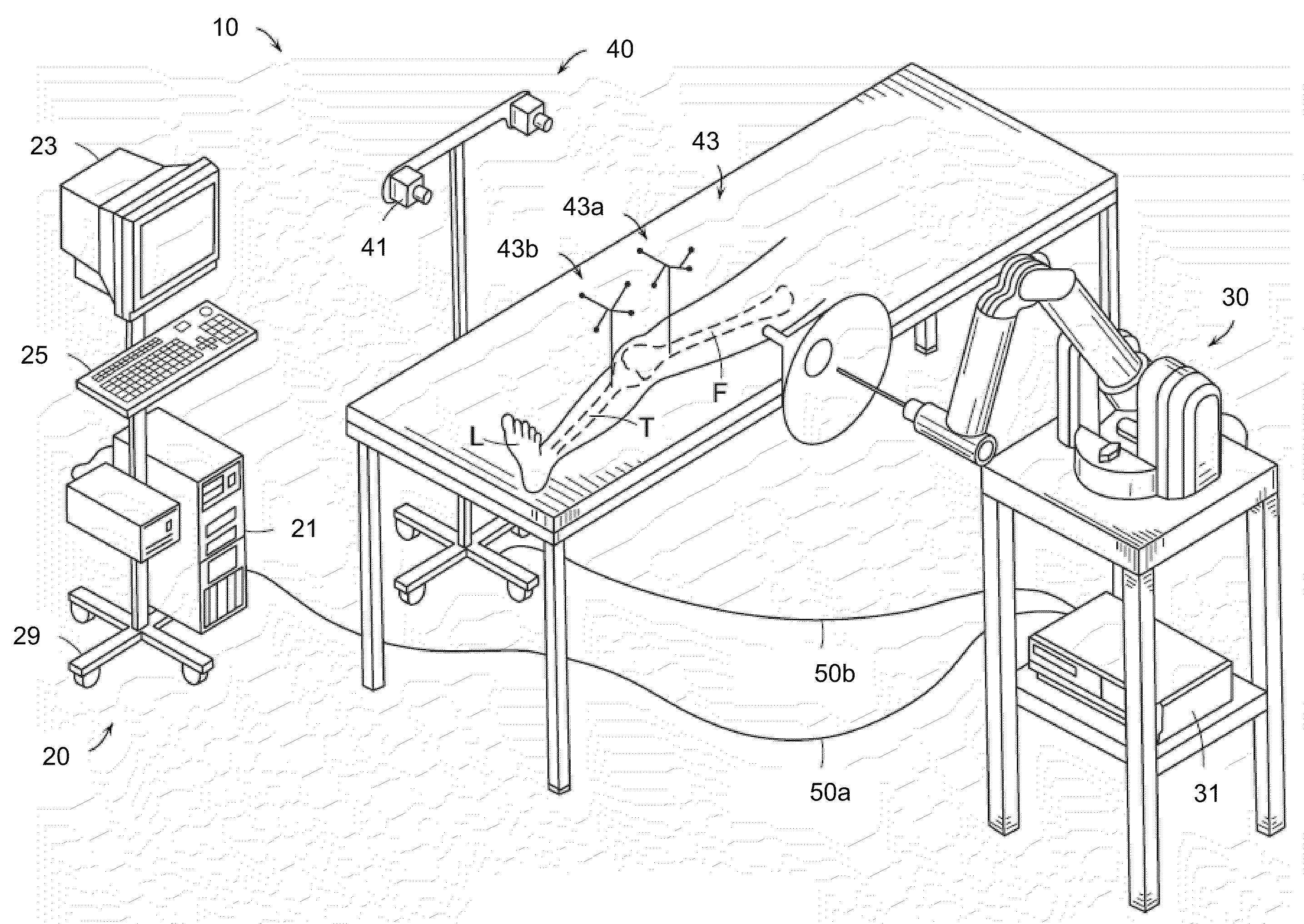
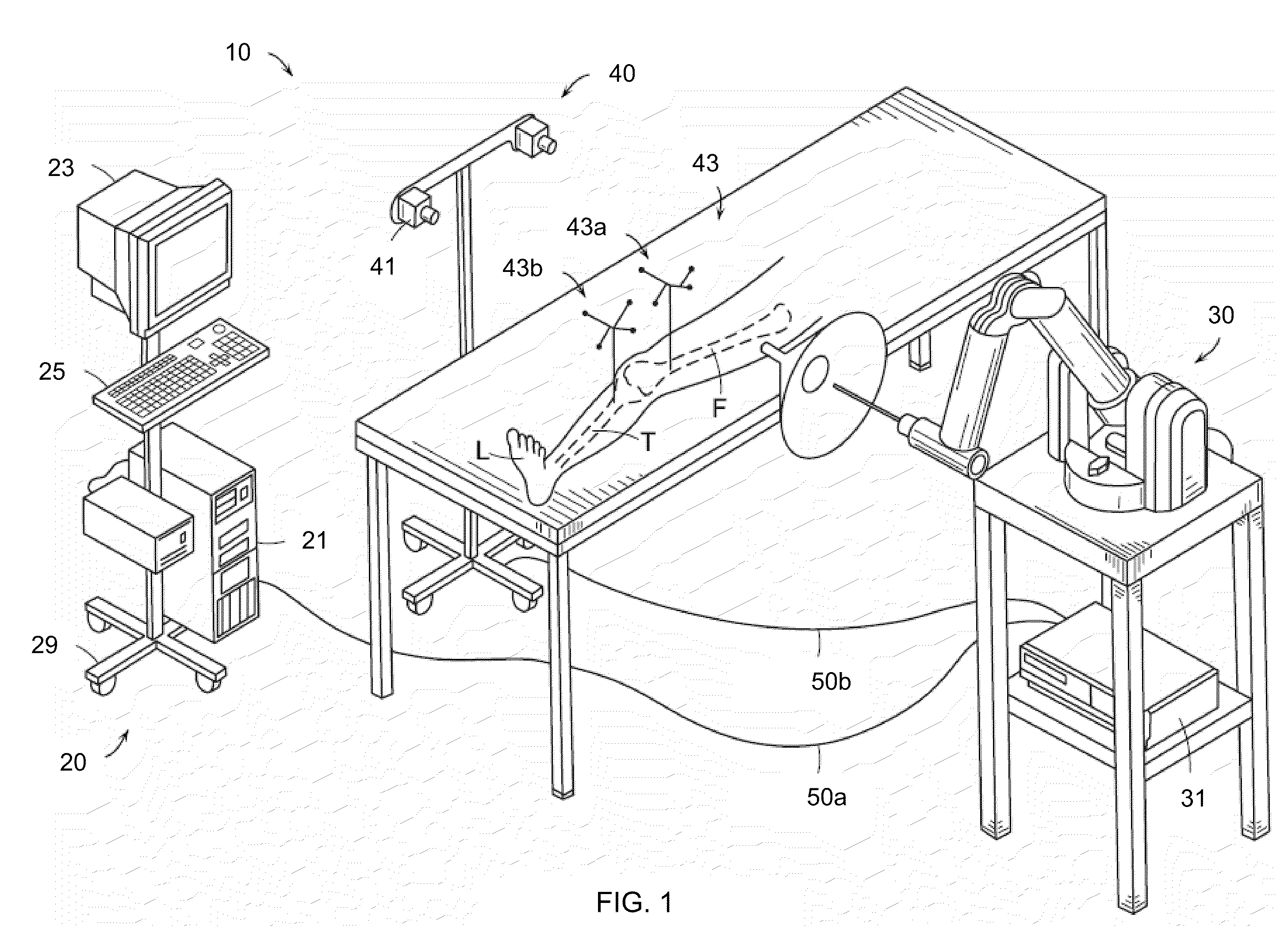
[0036]FIG. 1 shows an embodiment of an exemplary surgical computer system 10 in which the self-detecting kinematic clamp assembly and techniques described herein can be implemented. Such an exemplary system is described in detail, for example, in U.S. Patent Application Publication No. 2006 / 0142657, published Jun. 29, 2006, which is hereby incorporated by reference herein in its entirety. In a preferred embodiment, the surgical computer system is the TACTILE GUIDANCE SYSTEM™ or the RIO™, manufacture...


PUM


Abstract

Described are computer-based surgical methods and apparatuses for a self-detecting kinematic assembly. The self-detecting kinematic clamp assembly detects and indicates a degradation in pose. The self-detecting kinematic clamp assembly includes a tracking element for tracking a pose of the kinematic clamp assembly. The self-detecting kinematic clamp assembly includes a base portion comprising a fixation device that is attachable to a rigid body, and a top portion connected to the tracking element, the top portion being removably connected to the base portion. The self-detecting kinematic clamp assembly includes a detection mechanism, the detection mechanism including three or more contact points between the base potion and top portion and a mechanism that detects movement between one or more of the three or more contact points.

Description

CROSS REFERENCES TO RELATED APPLICATIONS[0001]This application relates to and is assigned to the same entity as the co-pending application identified by Attorney Docket No. M077, entitled “Fifth marker and kinematic clamp,” U.S. Provisional Patent Application No. 61 / 131,487, filed on Jun. 9, 2008, the disclosure of which is hereby incorporated herein by reference in its entirety.FIELD OF THE INVENTION[0002]The present invention relates generally to surgical systems and methods and, more particularly, to self-detecting kinematic clamp assemblies.BACKGROUND[0003]Orthopedic joint replacement surgery may involve arthroplasty of a knee, hip, or other joint (e.g., shoulder, elbow, wrist, ankle, finger, etc.). During joint replacement surgery, a surgeon typically removes diseased bone from the joint and replaces the resected bone with prosthetic implant components. Challenges of joint replacement surgery include determining the appropriate position for implant components within the joint r...

Claims


Application Information

Patent Timeline
IPC IPC(8): A61B5/05A61B19/00
CPCA61B19/5244A61B2017/00477A61B2017/00694A61B2019/5483A61B2019/4857A61B2019/5251A61B2017/00725A61B2090/3983A61B34/20A61B2090/0811A61B2034/2051
Inventor VAN VORHIS, ROBERTDUGAL, AMARDEEP SINGHPEREZ, TIMOTHY W.
Owner MAKO SURGICAL CORP
Why Eureka
Try Eureka