
Top layer for an absorbent product

a technology of absorbent products and top layers, applied in the field of absorbent products, can solve the problems of chafing on the wearer, crumpled side zones, and particularly great material choice for the top layer,

Inactive Publication Date: 2009-12-10
SCA HYGIENE PROD AB
View PDF2 Cites 27 Cited by
  • Summary
  • Abstract
  • Description
  • Claims
  • Application Information

AI Technical Summary

Benefits of technology

[0014]One advantage of the invention is that loose particles present under the top layer are prevented from finding their way out through the top layer via the holes, at the same time as holes are permitted in the first material layer, which confers the advantages described below.
[0015]Another advantage of the invention is that the first material layer can be manufactured separately and the second material layer can be manufactured separately, after which they are joined together in the desired manner.
[0016]According to one embodiment of the invention, the first material layer comprises two subsidiary layers arranged to either side of the second material layer, each subsidiary layer comprising a first part and a second part, where the first part and / or the second part contains holes, and where the first part is folded over the second part along a fold line, the first material layer being attached directly to the second material layer adjacent to the lines extending in the longitudinal direction in inner joining zones. The expression “to either side” is used here to denote a positioning of the subsidiary layers essentially in the same plane as the second material layer.
[0017]According to one embodiment of the invention, the first part contains holes and the second part lacks holes, which first part is folded over the second part in such a way that the holes are covered by the second part. The first part is arranged on the absorbent product in such a way that it faces towards a wearer during use. One advantage of this embodiment is that the top layer, as a consequence of the holes, takes on a textile feel in accordance with the prior art, but that loose particles present under the top layer are prevented from finding their way out through the top layer via the holes.
[0018]According to another embodiment of the invention, the second part contains holes and the first part lacks holes, which first part is folded over the second part in such a way that the holes are covered by the first part. The first part is arranged on the absorbent product in such a way that it faces towards a wearer during use. One advantage of this embodiment is that the top layer, as a consequence of the holes, permits the transport of a high volume of air between a subjacent material and the space that is formed between the first part and the second part, but that loose particles present under the top layer are prevented from finding their way out through the top layer via the holes. The space has the advantage that the space buffers the air, which is then able to diffuse out through an air-permeable first part.
[0019]Further advantages of this embodiment are that loose particles, for example superabsorbents or particulate odor inhibitors or the like, are able to pass through the holes into the space, where they can perform their absorbent effect in the envisaged manner, instead of leaking into the surroundings.

Problems solved by technology

The problems associated with the choice of material for the top layer are particularly great in the side zones, because the side zones of the absorbent product make contact at least partially with a wearer's groin.
The nature of the problem is that the groin moves relative to the side zones, which can give rise to chafing, and that the side zones become crumpled.
The movement in the side zones is usually less than the movement in the central zone, which can give rise to chafing on the wearer if an inappropriate material is used in the side zones.
One problem with holes is that the holes are always open and permit excessive reflux of moisture from the absorption body.
Another problem is that the holes permit leakage of material lying loosely under the top layer, for example superabsorbents (SAP), fibres, odor inhibitors, etc.
Any material lying loosely that has found its way out through the holes ends up between the absorbent product and the wearer's skin and can cause discomfort for the wearer, for example in the form of chafing.
The above-mentioned problems are especially great in the side zones of the absorbent product, because the movement of the side zones affects the absorption body in such a way that SAP and liquid tend to be transported out through the holes by the movement in the side zone.
Making the holes so small that the superabsorbents are not able to leak out through the holes, or so small that the moisture reflux problem is reduced, would reduce the transport of liquid from the top layer to the absorption body, that is to say the admission capacity of the top layer to the subjacent material, to an unacceptably low level.
Similar problems exist for all particles that risk leaking out through the holes, for example the above-mentioned particles.

Method used


Image

  • Top layer for an absorbent product
  • Top layer for an absorbent product
  • Top layer for an absorbent product

Examples


first embodiment

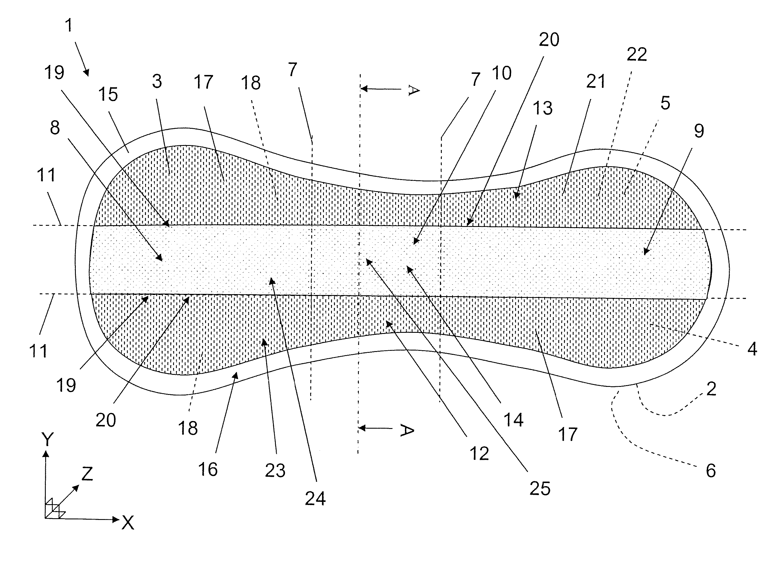
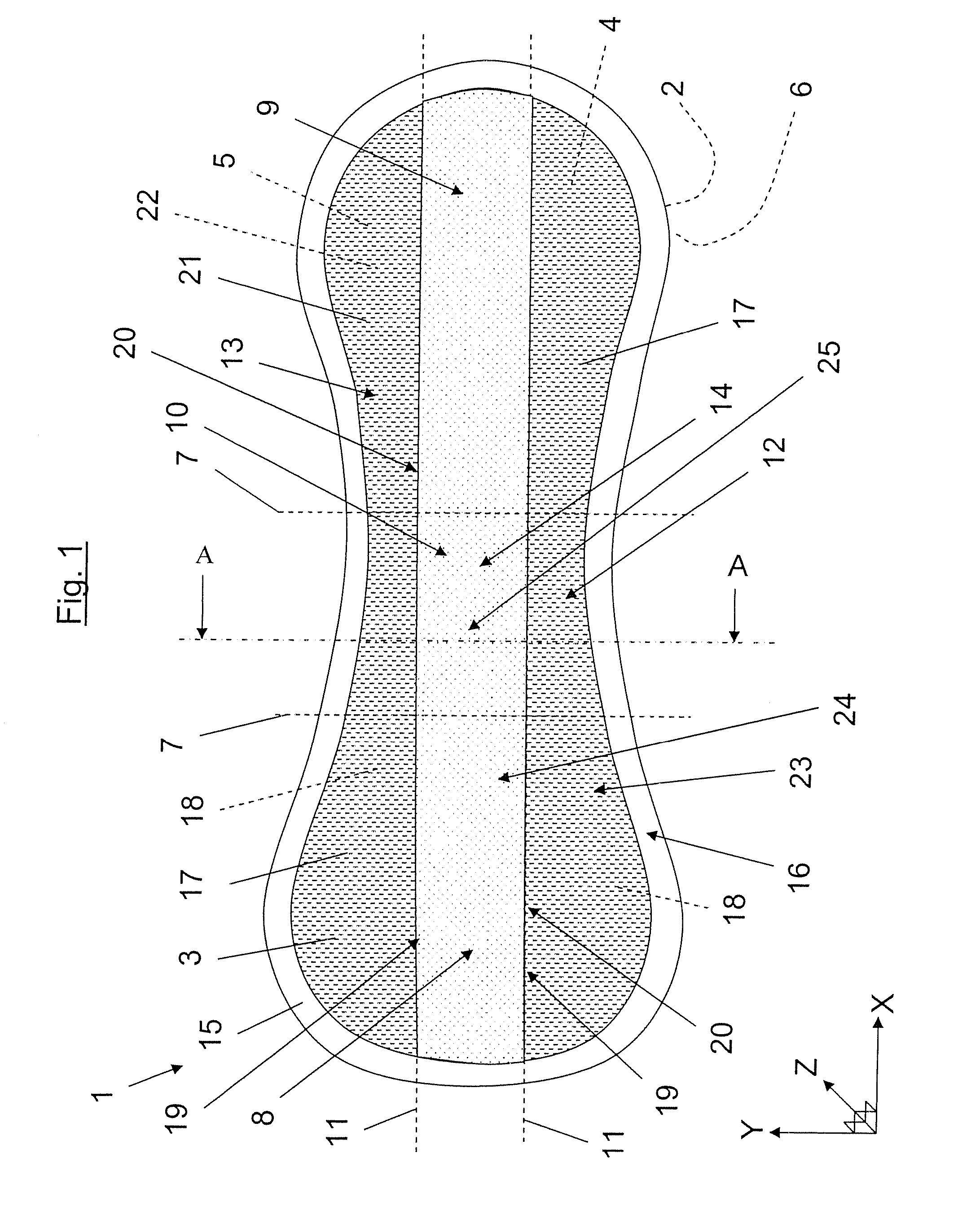
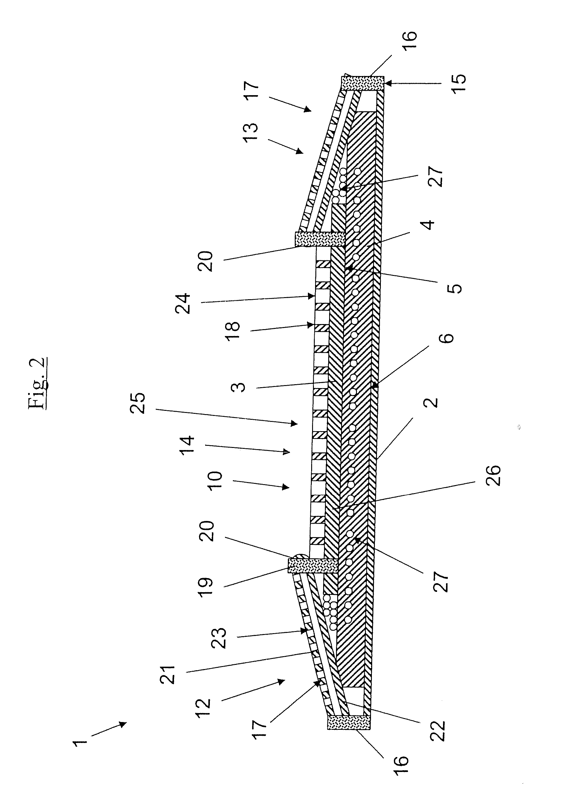
[0058]FIG. 2 depicts schematically a sectional view along the line A-A in FIG. 1 according to the invention. FIG. 2 shows that the side zones 12, 13 comprise the first material layer 17 double-folded and including the first part 21 containing a number of holes 23 and the second part 22 which lacks holes. The first part 21 is positioned on the top side of the absorbent product 1, that is to say on that part of the absorbent product 1 which is intended to face towards a wearer during use. The perforated first part 21 is intended here to give the material in the side zones 12, 13 a textile and comfortable feel for the wearer. The second part 22 is arranged between the first part 21 and the subjacent laminated structure consisting of a receiving layer 26, the absorption body 4 and the backing layer 2.

[0059]FIG. 2 shows that the absorption body 4 contains superabsorbents 27 (hereinafter referred to as SAP) in the form of small granules. FIG. 2 also shows that the SAP granules 27 have mig...

second embodiment

[0062]FIG. 3 depicts schematically a sectional view along the line A-A in FIG. 1 according to the invention. FIG. 2 and FIG. 3 are identical apart from the execution of the first material layer 17. FIG. 3 shows that the first part 21 is longer than the second part 22. The inner joining zones 19 bond the top layer 3 and the receiving layer 26 together at the point where the first material layer 17 has its fold line 20, that is to say along the longitudinally extending lines 11. The outer joining zone 16 bonds the first part 21 and the backing layer 2 together. The outer joining zone 16 can also contain the absorption body 4, in which case the edge part 15 possesses a softer feel than when only the top layer 3 and the backing layer 2 form the edge part.

[0063]FIG. 3 shows that the first part 21 and the second part 22 are joined together via interjacent joining zones 28 adjacent to the area where the second part 22 ends. The second part 22 ends at a predetermined distance between the fo...

third embodiment

[0064]FIG. 4 depicts schematically a sectional view along the line A-A in FIG. 1 according to the invention. FIG. 2 and FIG. 4 are identical apart from the execution of the first material layers. FIG. 4 shows that the first part 21 and the second part 22 have identical lengths, and that the inner joining zones 19 bond the top layer 3 and the receiving layer 26 together at the point where the first material layer 17 has its fold line 20, that is to say along the longitudinally extending lines 11. The outer joining zone 16 bonds the first part 21, the second part 22 and the backing layer 3 together. The outer joining zone 16 can also contain the absorption body 4, in which case the edge part 15 possesses a softer feel than when only the top layer 3 and the backing layer 2 form the edge part.

[0065]FIG. 4 shows that the first part 21 lacks holes, and that the second part contains the holes 23. The first part 21 is positioned on the upper side of the absorbent product, that is to say on ...


PUM


Abstract

An absorbent product such as a panty liner, incontinence pad, sanitary towel or the like comprising a top layer consisting of a first material layer and a second material layer, the first material layer being attached directly to the second material layer. The first material layer has a first part and a second part, where the first part and / or the second part contains openings, and where the first part is folded over the second part along a fold line, the first material layer being attached directly to the second material layer adjacent to at least one line extending in the longitudinal direction in an inner joining zone. A method for the manufacture of an absorbent product of this kind.

Description

TECHNICAL FIELD[0001]The invention relates to an absorbent product such as a panty liner, incontinence pad, sanitary towel or the like comprising a top layer consisting of a first material layer and a second material layer. The first material layer is attached directly to the second material layer. The absorbent product exhibits two lines extending in the longitudinal direction, which divide the product in a lateral direction in such a way that the product exhibits a first side zone, a second side zone and positioned between them a central zone. The invention also relates to a method for the manufacture of an absorbent product of this kind.BACKGROUND ART[0002]In previously disclosed absorbent products, the top layer comprises a material layer that is liquid-permeable in order to be able to transport liquid from the top layer to the subjacent absorption body. The liquid can be menstrual fluid or urine, and the choice of the material used for the top layer depends on which of these li...

Claims


Application Information

Patent Timeline
IPC IPC(8): A61F13/15
CPCA61F13/4755A61L15/60A61L15/425A61F13/512
Inventor OLSSON, KEN
Owner SCA HYGIENE PROD AB
Learn More