Test equipment for testing hazard detectors

a technology for testing equipment and detectors, applied in measurement devices, instruments, material analysis through optical means, etc., can solve the problems of wasting time, cumbersome and time-consuming, etc., and achieve the effect of reducing time consumption, reducing labor intensity, and saving time in testing

Active Publication Date: 2009-12-17
SATA GMBH & CO KG
View PDF4 Cites 41 Cited by
  • Summary
  • Abstract
  • Description
  • Claims
  • Application Information

AI Technical Summary

Benefits of technology

[0022]When used for testing single sensor detectors, it has the advantage that it permits a single test tool to be used. For example, the user does not need to carry more than one test tool, swapping between a smoke detector testing tool and a heat detector testing tool when encountering both types in succession. Instead, he can use the one tool, and simply deploy the required stimulus to the detector in question. This will save much time in testing and maintaining even single sensor hazard detectors, where often many must be tested in succession. It is also much more convenient for the user to only have one piece of equipment to carry.
[0023]When the apparatus is used for testing multisensor hazard detectors which contain any combination of heat, smoke or CO sensors, it now becomes practically possible to test each individual sensor within the detector using just one tool, so that full operation of the detector is verified swiftly and efficiently. To test such detectors with multiple tools would be very cumbersome and time-consuming, and may even be impossible should the detector require more than one sensor to be activated simultaneously during a test. Moreover, in the case of the present invention, even deploying multiple stimuli simultaneously would be theoretically possible, thereby not only properly testing the individual sensors within a multisensor hazard detector but within the shortest possible time. (Note: this requires that the hazard detector can be configured to permit such a test.)
[0029]Such detectors are often sufficiently advanced to be able to distinguish between various real stimuli and ‘false’ stimuli so as to minimise the occurrence of false alarms. For example, some fire detectors can distinguish between smoke and steam, in an attempt to reduce the number of false alarms from smoke detectors fitted in areas where steam might be prevalent (such as shower or bath rooms, kitchens, etc.).

Problems solved by technology

This will save much time in testing and maintaining even single sensor hazard detectors, where often many must be tested in succession.

Method used


Image

  • Test equipment for testing hazard detectors
  • Test equipment for testing hazard detectors
  • Test equipment for testing hazard detectors

Examples


Embodiment Construction

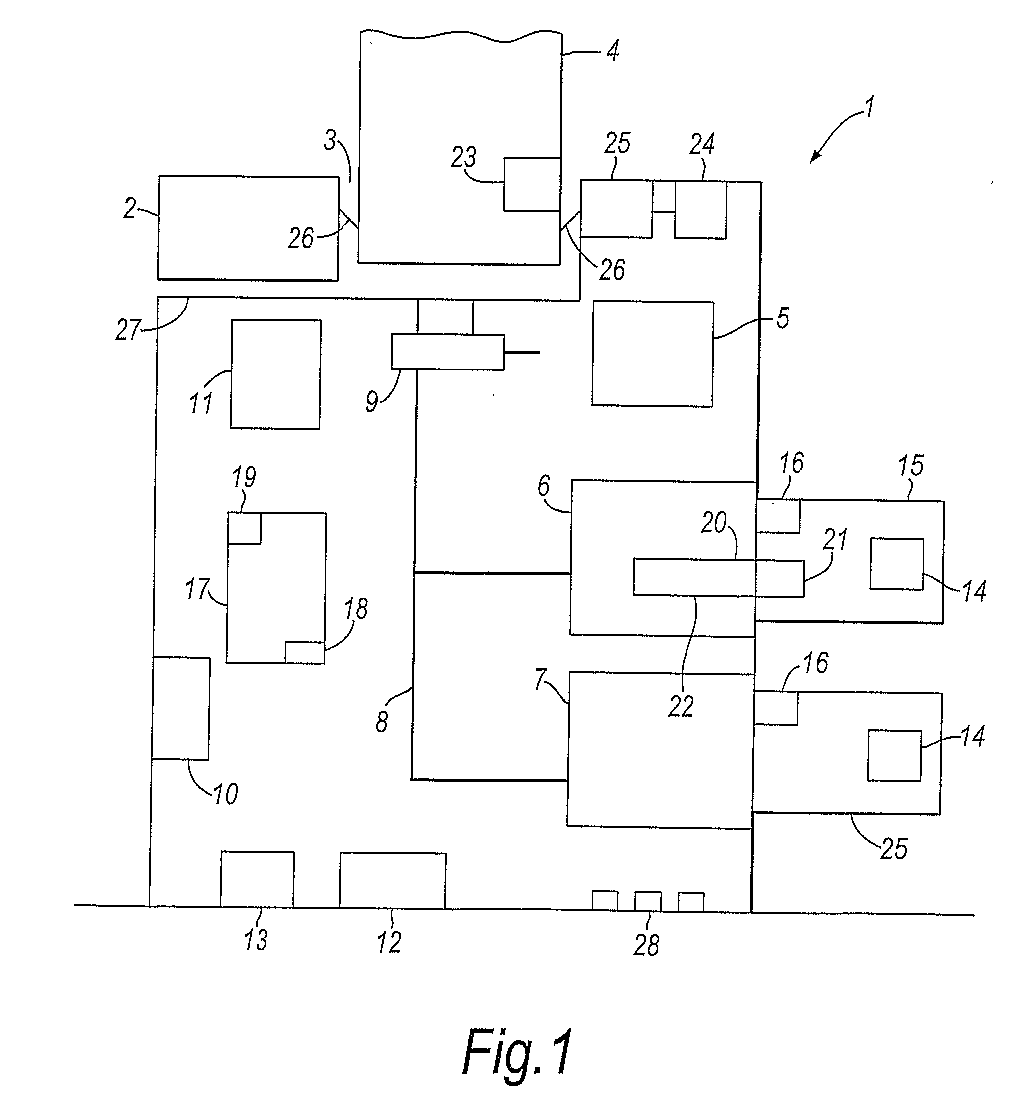
[0037]Referring now to FIG. 1 which shows a schematic diagram of the test tool according to a first embodiment of the present invention. It will be appreciated that this diagram is representative of the tool and it various components and is not limiting on the structure of the tool and arrangement of its components. The test tool 1 includes an outer housing 2 which includes an opening 3. The opening is generally cup-shaped and is arranged to receive a detector / sensor 4. The actual dimensions and configuration of the housing and opening will depend on the type of detector / sensor the tool is intended for use with. A number of stimulus generating units 5, 6 and 7 are positioned within the tool. In this case, the tool is provided with a heat generator 5, a smoke generator 6 and a carbon monoxide generator 7.

[0038]Ducts 8 are provided between the stimulus generating units 5, 6 and 7 and the opening 3. The tool utilises fans and / or blowers 9 to move generated stimuli (e.g. smoke) in the d...


PUM

PropertyMeasurementUnit
distanceaaaaaaaaaa
distanceaaaaaaaaaa
temperatureaaaaaaaaaa

Abstract

Apparatus for testing a hazard detector, the apparatus comprising electrically-powered generating means arranged to generate at least two stimuli for application to the detector; and control means arranged to control the generation of each stimulus by said stimulus generating means, wherein said generating means includes a carbon monoxide generator.

Description

[0001]The present invention relates to hazard detector test equipment and in particular hazard detector test equipment which produces stimuli for such detectors.BACKGROUND TO THE INVENTION[0002]Hazard detection systems can utilise a variety of sensors to detect hazards, including smoke sensors, heat sensors, gas sensors, etc. Equipment to carry out testing of different types of hazard detector is already available worldwide, and a well-known brand is ‘SOLO’ test equipment. In the past, each hazard sensor has often been housed in its own separate hazard detector, and test equipment to execute the testing of such detectors has mainly used a single test stimulus to activate the sensor concerned, e.g. a heat source is used in an item of test equipment to test a heat detector, etc. The test stimulus (heat, in this example) is designed to replicate the hazard in a non-hazardous fashion, so that the correct operation of the detector and / or the system can be verified without the risk of dup...

Claims


Application Information

Patent Timeline
Patent Type & Authority Applications(United States)
IPC IPC(8): G01N33/00G01N37/00
CPCG08B29/145G08B29/12
Inventor PEPPER, STEWART
Owner SATA GMBH & CO KG
Why Eureka
Try Eureka