Acoustic Inhaler Flow Measurement
- Summary
- Abstract
- Description
- Claims
- Application Information
AI Technical Summary
Benefits of technology
Problems solved by technology
Method used
Image

Examples
first embodiment
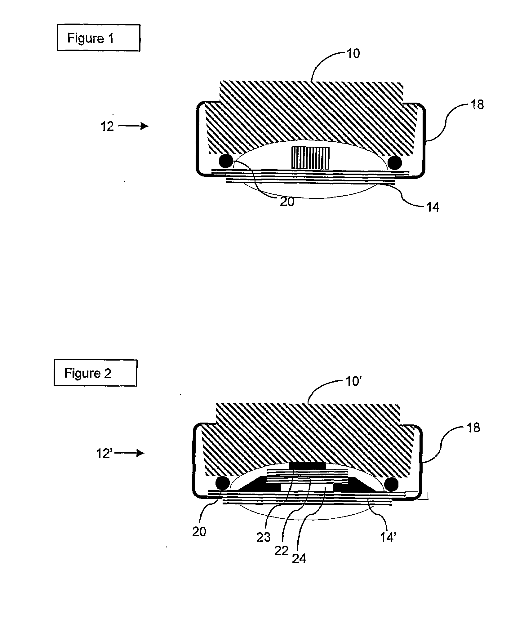
[0043]FIG. 1 illustrates a cross section of an inhaler with a sensor,
second embodiment
[0044]FIG. 2 illustrates a cross section of an inhaler with a sensor,
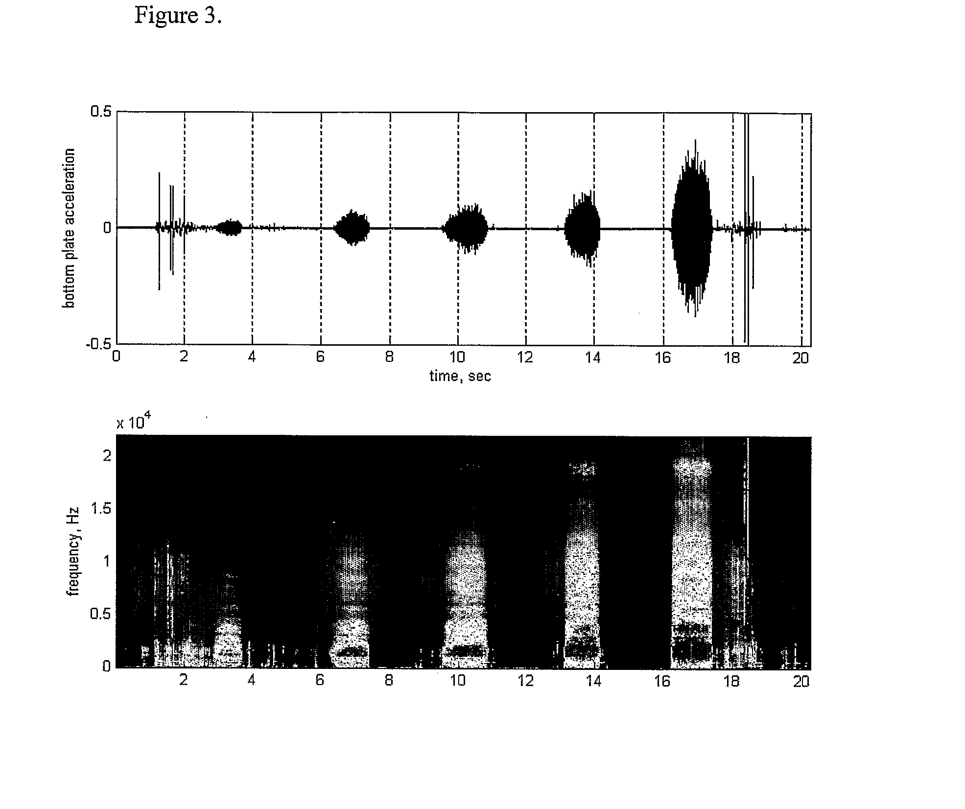
[0045]FIG. 3 illustrates the variation of a sound spectrum with flow rate,
[0046]FIG. 4 illustrates an interesting manner of determining a torque between two elements,
[0047]FIG. 5 illustrates a cross section through the embodiment of FIG. 4.
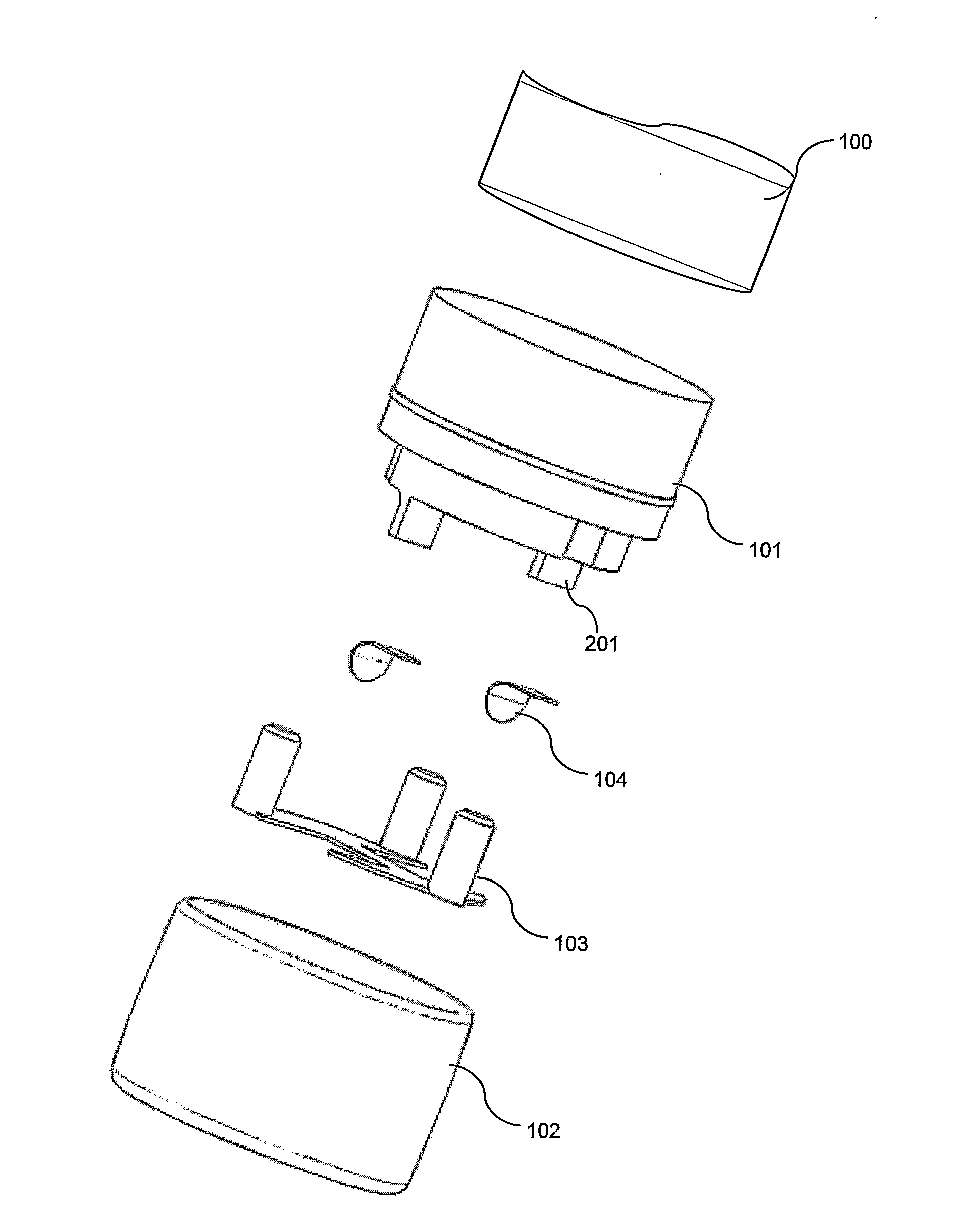
[0048]FIG. 1 illustrates a cross section through a first embodiment of an inhaler 10, which may be any Inhaler, such as the Diskus® (GSK), Technohaler® (Innovata Biomed), D2L® (Ivax), Turbuhaler® (AstraZeneca), SkyeHaler DPI® (SkyePharma), Easi-Breathe DP® (IVAX), Pulvinal® (Chiesi), EasyHaler® (Orion Farmos), Clickhaler® (Innovata Biomed), Taifun® (Focus Inhale), or the Ultrahaler® (Aventis). At the bottom (or at any other suitable position), a sensor assembly 12 is provided which comprises an element 14 holding a microphone 16 and which is fastened via a fastening clip 18 to the bottom of the inhaler 10. Between the element 14 and the bottom, a resilient element 20 is provided ...
PUM
 Abstract
Description
Claims
Application Information
 - R&D
- Intellectual Property
- Life Sciences
- Materials
- Tech Scout
- Unparalleled Data Quality
- Higher Quality Content
- 60% Fewer Hallucinations
Browse by: Latest US Patents, China's latest patents, Technical Efficacy Thesaurus, Application Domain, Technology Topic, Popular Technical Reports.
© 2025 PatSnap. All rights reserved.Legal|Privacy policy|Modern Slavery Act Transparency Statement|Sitemap|About US| Contact US: help@patsnap.com