Particle therapy system

a particle therapy and system technology, applied in the field of particle therapy system, can solve the problems of large uncertainty in the planning of the based radiation room, difficulty in connecting the gantry-based radiation room to the accelerator unit at the same height, etc., and achieve the effect of easy planning and construction

Inactive Publication Date: 2009-12-17
SIEMENS AG
View PDF7 Cites 20 Cited by
  • Summary
  • Abstract
  • Description
  • Claims
  • Application Information

AI Technical Summary

Benefits of technology

[0009]The present embodiments may obviate one or more of the drawbacks or limitations in the related art. For example, the present embodiments may related to providing a particle therapy system and a method for building such a system which allow easy planning and easy construction, in particular when the system is to include a gantry-based radiation room. A method for retrofitting a particle therapy system may also be provided. The method may be used to enable the retrofitting to be carried out in a simple manner.

Problems solved by technology

Connecting a gantry-based radiation room to the accelerator unit at the same height can sometimes be problematic because the axis of rotation of the gantry essentially lies at the same height as the accelerator unit.
A gantry-based radiation room having an axis of rotation that lies at this height creates the problem that the gantry-based radiation room must be set considerably deeper on account of the projecting gantry than, for example, other radiation rooms or rooms for the accelerator.
This may be problematic when the gantry-based radiation room is to be retrofitted.
The foundations would have to be excavated retrospectively to a greater depth at great expense, which, owing to the sensitivity of the system, can also result in downtimes or be planned and built to be deep enough from the outset to allow the retrofit.
The latter may only be planned with a large measure of uncertainty if the gantry specifications are not known precisely.
Even without retrofitting, however, the costs for the construction of the building are lower if the foundations are set to a lower depth.

Method used


Image

  • Particle therapy system
  • Particle therapy system
  • Particle therapy system

Examples


Embodiment Construction

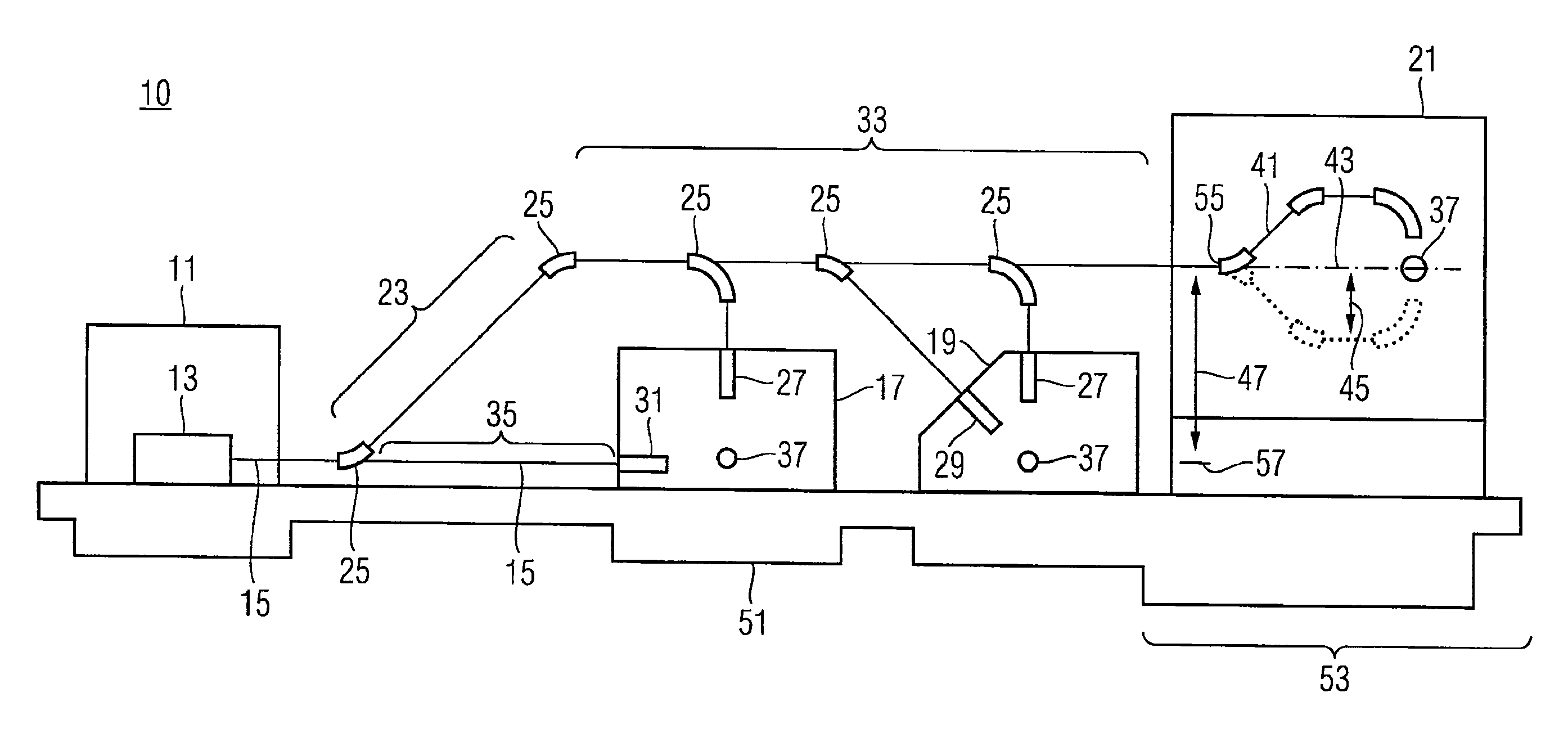
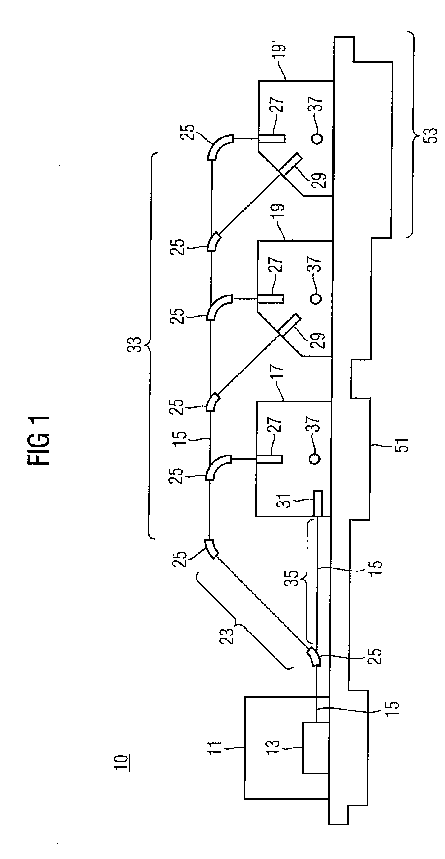
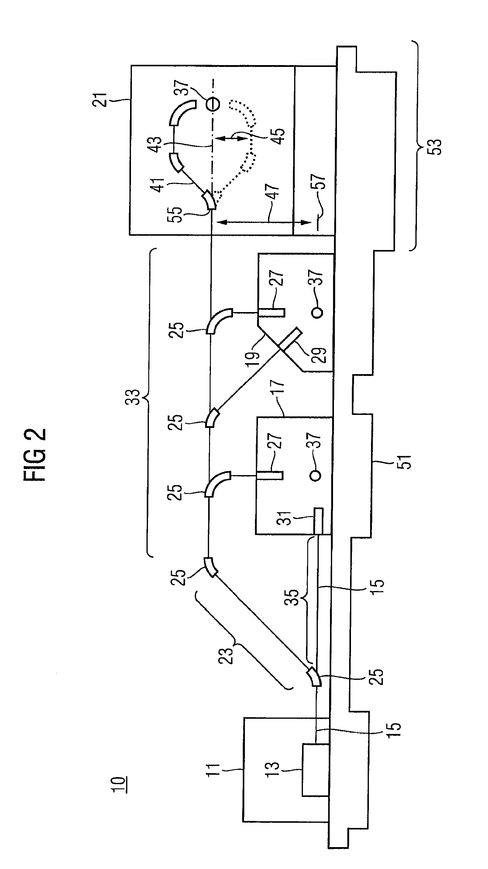
[0028]FIG. 1 shows a particle therapy system 10 in a schematic side view. Located in a first section 11 is the accelerator unit 13 by which charged particles are generated and accelerated to the energy necessary for irradiation purposes, and by which a particle beam is formed.

[0029]After having been provided by the accelerator unit 13, the particle beam enters the particle beam transport system 15. The particle beam is guided, using the transport system 15, from the accelerator unit 13 to the radiation rooms 17, 19, 19′. Any deflection of the particle beam may be necessary is effected by a suitable setting of the various deflection magnets 25 in the particle beam transport system.

[0030]Immediately after the particle beam enters the particle beam transport system 15, given an appropriate setting of the deflection magnets 25, the particle beam may be guided into a first subarea 23 of the particle beam transport system 15, as a result of which the particle beam is guided out from the l...


PUM

PropertyMeasurementUnit
heightaaaaaaaaaa
heightaaaaaaaaaa
sizeaaaaaaaaaa

Abstract

The present embodiments relate to a particle therapy system having an accelerator unit for providing a particle beam and having a particle beam transport system for guiding the particle beam. The particle beam transport system has a first subarea by which the particle beam can be guided out from a level of the accelerator unit. A gantry-based radiation room is connected to the first subarea of the particle beam transport system. The present embodiments may also relate to a particle therapy system having foundations, where the foundations are dimensioned at one point such that a gantry-based radiation room can be retrofitted at the one point. In particular the foundations at the one point are located essentially at the same height as the foundations underneath an accelerator unit and/or underneath a particle beam transport system.

Description

[0001]The present patent document claims the benefit of the filing date of DE 10 2008 028 510.2, filed Jun. 16, 2008, which is hereby incorporated by reference.BACKGROUND[0002]The present embodiments relate to retrofitting a particle therapy system.[0003]Particle therapy systems are used for treating tumor diseases. Particle therapy is a method for treating tissue, such as tumor diseases. Irradiation methods used in particle therapy are also used in non-therapeutic fields, however. These non-therapeutic fields include, for example, particle therapy research activities that are carried out on non-living phantoms or bodies, irradiation of materials, etc. Charged particles, such as protons or carbon ions or other types of ions, are accelerated to high energies, formed into a particle beam, and guided via a high-energy beam transport system to one or more radiation rooms. Once in the radiation room, the object that is to be irradiated is irradiated with the particle beam.[0004]Radiation...

Claims


Application Information

Patent Timeline
Patent Type & Authority Applications(United States)
IPC IPC(8): B01J19/12B23P11/00
CPCA61N5/10Y10T29/49826A61N2005/1087A61N5/1079
Inventor GUNZERT-MARX, KONSTANZEHANSMANN, THOMASKAISER, WERNERMULLER, TOBIAS
Owner SIEMENS AG
Why Eureka
Try Eureka