Capacitive touch panel

a touch panel and capacitive technology, applied in the field of capacitive touch panels, can solve the problems of damage to the sensitivity and precision of the capacitive sensing signal, and achieve the effect of improving the sensitivity and the precision of the capacitive sensing

Inactive Publication Date: 2009-12-17
YOUNG FAST OPTOELECTRONICS
View PDF8 Cites 139 Cited by
  • Summary
  • Abstract
  • Description
  • Claims
  • Application Information

AI Technical Summary

Benefits of technology

[0003]Accordingly, the present invention provides a touch panel structure with the X and Y axis traces in a same plane so as the traces can be formed more precisely to improve the sensitivity and the precision of the sensing effect.

Problems solved by technology

The panel will not repeatedly sustain stress and then deforms and it damaged because an input is performed without strongly pressing on the panel.
When assembling the X and Y sensing traces of the two different layers, a misalignment is happened and the sensitivity and precision of the sensing signal of the capacity will be damaged.

Method used


Image

  • Capacitive touch panel
  • Capacitive touch panel
  • Capacitive touch panel

Examples


Embodiment Construction

[0014]In order that those skilled in the art can further understand the present invention, a description will be provided in the following in details. However, these descriptions and the appended drawings are only used to cause those skilled in the art to understand the objects, features, and characteristics of the present invention, but not to be used to confine the scope and spirit of the present invention defined in the appended claims.

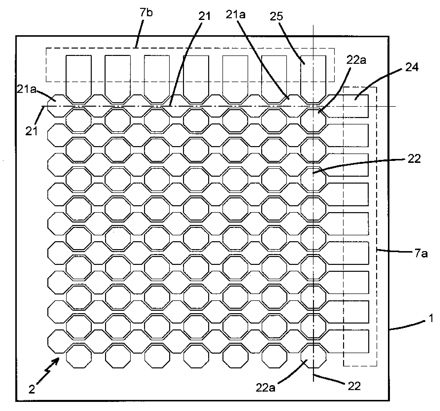
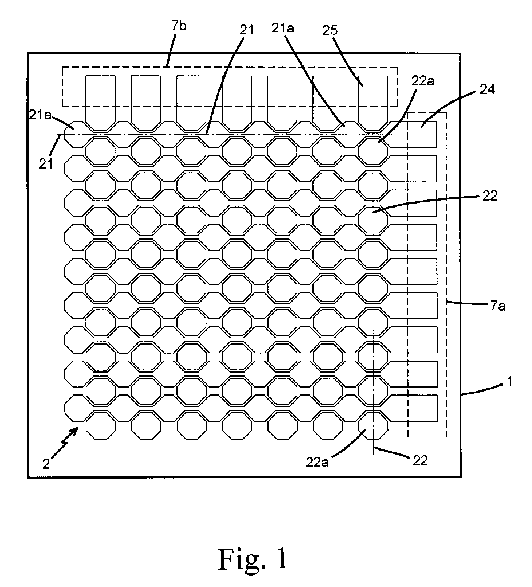
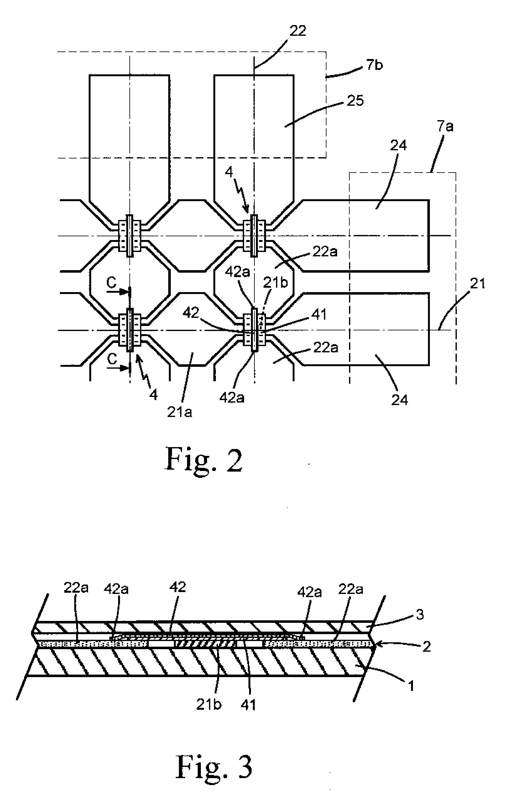
[0015]As shown in FIGS. 1 to 3, the first embodiment shown in the figures is a capacitive touch panel made of a transparent panel and the panel consists of a substrate layer 1, sensing layer 2, surface layer 3, and a bridge structure 4. The substrate layer 1 and the surface layer 3 are insulated thin panels with highly transparent property such as a material of glass, Polycarbonate (PC), Polythylene terephthalate (PET), Polymethylmethacrylate (PMMA), or Cyclic Olefin Copolymer. The sensing layer 2 is made of a transparent conductive film such as an...


PUM


Abstract

A capacitive touch panel is assembled by a substrate layer, sensing layer, and surface layer. A plurality of transparent X and Y axis traces are arranged on the sensing layer and intersect each other as a matrix. A front end of each X trace and each Y trace has a joint. The plurality of X axis traces and Y axis traces are arranged at the same plane. Each X axis trace includes a plurality of induction-spots and each Y axis trace includes a plurality of induction-spots. The induction-spots of one X axis trace are connected one by one, while the induction-spots of one Y axis trace are formed separately with gaps. The adjacent induction-spots of Y axis trace are connected by a bridge structure and the induction-spots of the Y axis trace are insulated to the respective one of the plurality of X axis trace.

Description

FIELD OF THE PRESENT INVENTION[0001]The present invention relates to capacitive touch panels, and in particular to a capacitive touch panel with X and Y axis traces formed on the same plane.DESCRIPTION OF THE PRIOR ART[0002]A prior capacitive touch panel structure includes an X axis sensing layer and a Y axis sensing layer and both of them are arranged inside the touch panel and insulated from each other. The X and Y sensing layers are grounded and connected to a control circuit respectively. When operating, an instant capacity effect is generated by a conductor or a user's finger touch so that the position being touched will be located by detection of the variation of capacitance. The capacitive touch panel is capable of being operated by human finger, and therefore, it is convenient for an input operation. The panel will not repeatedly sustain stress and then deforms and it damaged because an input is performed without strongly pressing on the panel. Moreover, the assembly of the ...

Claims


Application Information

Patent Timeline
Patent Type & Authority Applications(United States)
IPC IPC(8): G06F3/044
CPCG06F2203/04111G06F3/044G06F3/0443G06F3/0446
Inventor YANG, KAI-TI
Owner YOUNG FAST OPTOELECTRONICS
Why Eureka
Try Eureka