Glass-wiping device

a glass-wiping device and glass-wiping technology, which is applied in the direction of vehicle maintenance, vehicle cleaning, cleaning equipment, etc., can solve the problems of high hardware cost of glass-wiping devices, no edge detection function of all glass-wiping devices available in the market, and relatively complicated detection process. , to achieve the effect of reducing cost, simple structure and high sensitivity

Active Publication Date: 2019-01-08
ECOVACS ROBOTICS (SUZHOU ) CO LTD
View PDF29 Cites 0 Cited by
  • Summary
  • Abstract
  • Description
  • Claims
  • Application Information

AI Technical Summary

Benefits of technology

[0005]To overcome the deficiencies in the prior art, the present invention aims to provide a glass-wiping device that has a simplified structure, a reduced cost, a high sensitivity, and a great controllability and can effectively implements the detection of the edges of a plate glass.
[0015]To perform an accurate detection on the edge of plate glass and improve the sensitivity and precision of the detection system, a plurality of the edge detection units are provided, and the sensor switch in each of the edge detection units is connected to the control unit.
[0017]In conclusion, because of simplified structure, reduced costs and great controllability, the present invention can effectively realize the detection on the edge of plate glass.

Problems solved by technology

This detection manner is relatively complicated in process and needs a relatively high requirement for the hardware cost of the glass-wiping device.
Further, all the glass-wiping devices available in the market have no edge detection function, and in particular for a plate glass having no frame, have a risk of falling off.

Method used


Image

  • Glass-wiping device
  • Glass-wiping device

Examples


first embodiment

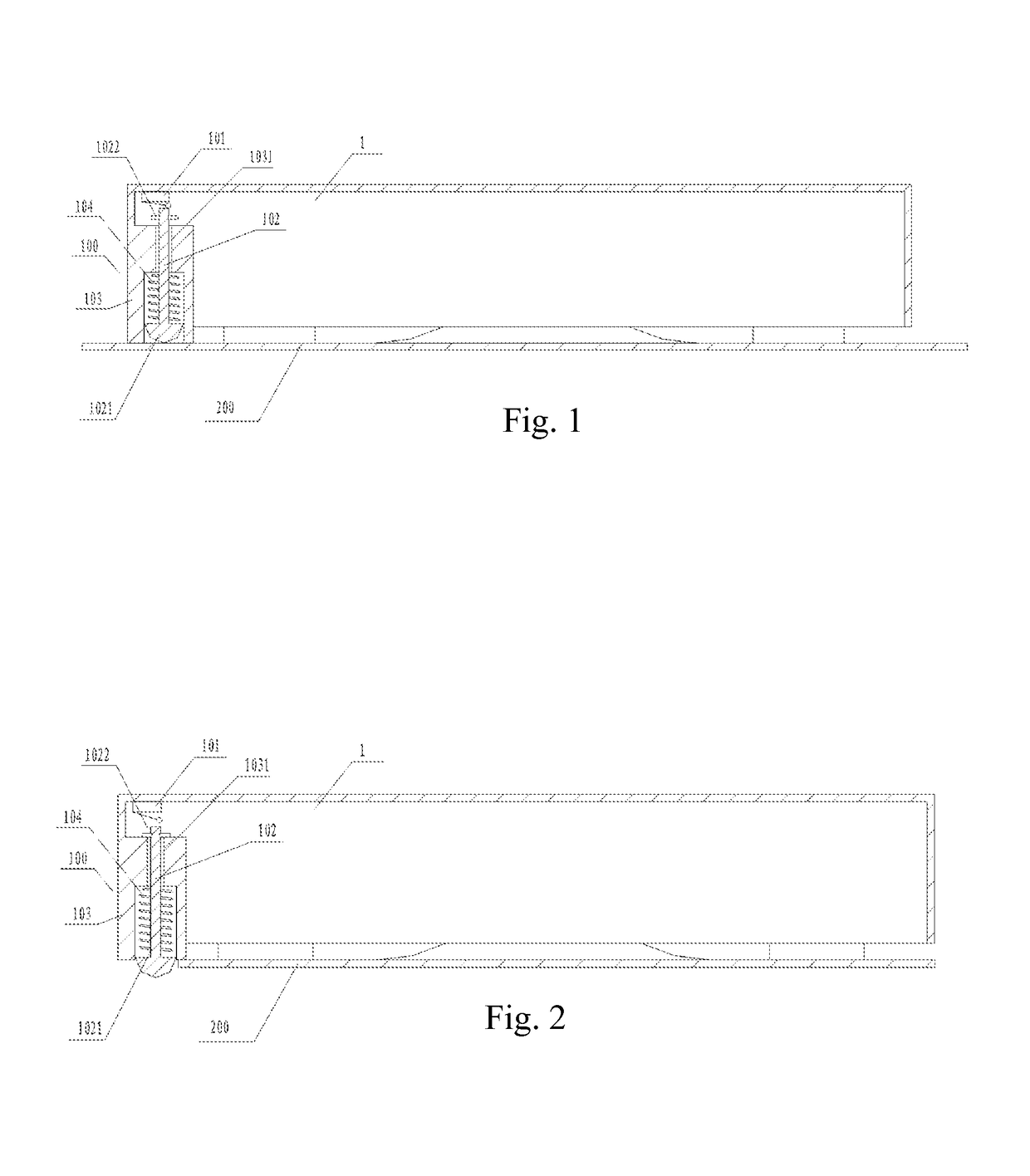
[0023]FIG. 1 is one structure diagram of the first embodiment of the present invention. As shown in FIG. 1, the present invention provides a glass-wiping device comprising a machine body 1 and a control unit. The machine body refers to the integral structure of the glass-wiping device including a suction mechanism, a running mechanism, an actuating mechanism and the like. The control unit refers to an integral control unit provided on the glass-wiping device to control the respective operations of the mechanisms in the glass-wiping device as well as the coordination operations between these mechanisms. An edge detection unit 100 is provided on the edge of the machine body 1, and comprises a sensor switch 101 and an action element 102. The action element 102 is provided at a lower end thereof with a contact leg 1021 that presses against the surface of a glass. When the contact leg 1021 leaves the surface of the glass 200, the action element 102 correspondingly generates a displacemen...

second embodiment

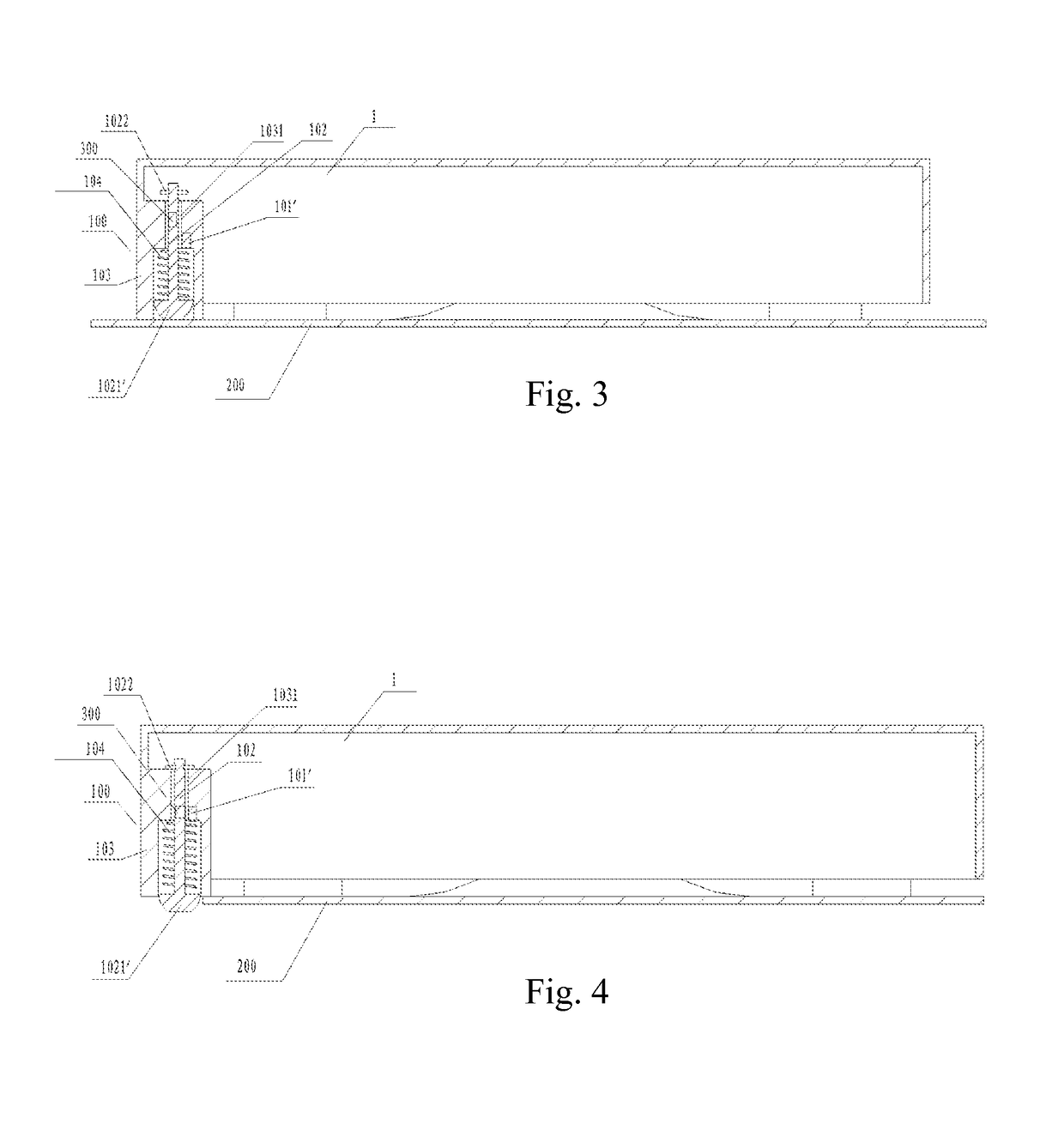
[0030]FIGS. 2 and 3 are two structure diagrams of the second embodiment of the present invention. As shown in FIG. 3 in combination with FIG. 4, in this embodiment, in order to improve sensitivity, the sensor switch 101′ is a Hall sensor and is provided on the supporting body 103. The action element 102 comprises a magnetic element 300 correspondingly provided thereon. Alternatively, the sensor switch 101′ is a magnetron, and the action element 102 comprises a magnetic element 300 correspondingly provided thereon.

[0031]The external shape of the glass-wiping device in this embodiment is a circular shape, and includes four edge detection units 100 evenly provided on the circumference. The action element 102 is arranged in the step through-hole 1031 of the detection unit supporting body 103. The upper and lower ends of this step through-hole are opened. The shape of the step through-hole 1031 is provided corresponding to the shape of the action element 102, so as to limit the movement ...


PUM


Abstract

A glass-wiping device comprises a machine body (1) and a control unit. The machine body (1) is provided with an edge detection unit (100), the edge detection unit (100) comprises a sensor switch (101, 101′) and an action element (102). The action element (102) is provided at a lower end thereof with a contact leg (1021, 1021′) that presses against the surface of a glass (200). When the contact leg (1021, 1021′) leaves the surface of the glass (200), the action element (102) correspondingly generates a displacement and triggers the sensor switch (101, 101′); the sensor switch (101, 101′) transmits a switch signal to the control unit; the control unit controls, on the basis of the switch signal, the glass-wiping device to cease running or to change the running direction. The glass-wiping device has a simple structure, reduced costs, high sensitivity and great controllability, and effectively implements the detection of the edge of a plate glass.

Description

BACKGROUND[0001]Field of the Invention[0002]The present invention relates to the technical field of the manufacture of small household electric appliances, and in particular relates to a glass-wiping device.[0003]Background of the Invention[0004]The glass-wiping robot has been widely used for its small and exquisite structure and flexible control. The method adopted by all the glass-wiping devices in the prior art to detect the glass frame and edge is as follows: first, performing a wavelet decomposition on an acquired image to obtain a histogram of the low frequency part of the image, and determining a threshold value of image blurring by a wavelet analysis on the histogram; then, defining a new membership function according to the threshold, and converting the image into an equivalent fuzzy property plane to conduct an enhancement mathematical operation and obtain the enhanced image; finally, completing edge detection and identification for the enhanced image. This detection manne...

Claims


Application Information

Patent Timeline
Patent Type & Authority Patents(United States)
IPC IPC(8): A47L1/02B60S1/04H01H3/16
CPCA47L1/02H01H3/16B60S1/0455A47L2201/04
Inventor LV, XIAOMING
Owner ECOVACS ROBOTICS (SUZHOU ) CO LTD
Why Eureka
Try Eureka