Liquid crystal display device

Active Publication Date: 2009-12-17
SAMSUNG ELECTRONICS CO LTD
View PDF5 Cites 27 Cited by
  • Summary
  • Abstract
  • Description
  • Claims
  • Application Information

AI Technical Summary

Benefits of technology

[0037]Each of the LCD devices with the constructions described above according to the present general inventive concept has an advantage of not being degraded even when used outdoors and, therefore, is effectively applicable r

Problems solved by technology

The light source in the backlight unit not only emits light but also generates heat to cause degradation of liquid crystals.
Thus, when the LCD device is used outdoors, a front side of the liquid crystal panel is expose

Method used


Image

  • Liquid crystal display device
  • Liquid crystal display device
  • Liquid crystal display device

Examples


Embodiment Construction

[0050]Reference will now be made in detail to embodiments of the present general inventive concept, examples of which are illustrated in the accompanying drawings, wherein like reference numerals refer to the like elements throughout. The embodiments are described below to explain the present general inventive concept by referring to the figures.

[0051]A description will be given of an exemplary embodiment of the present general inventive concept with reference to FIGS. 1 to 3.

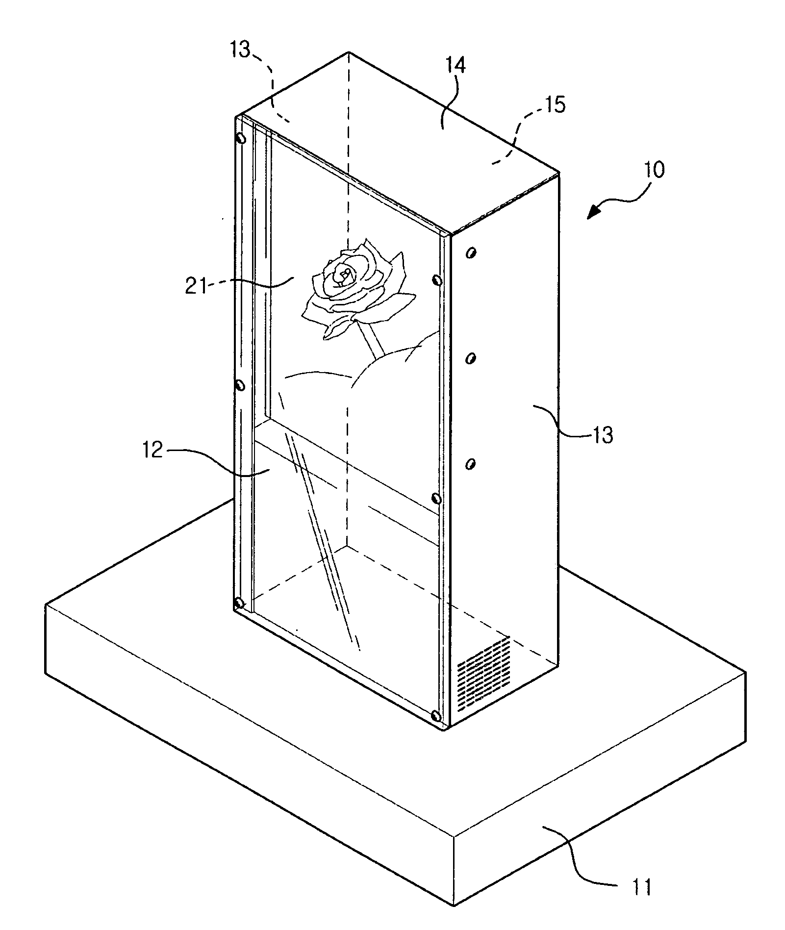
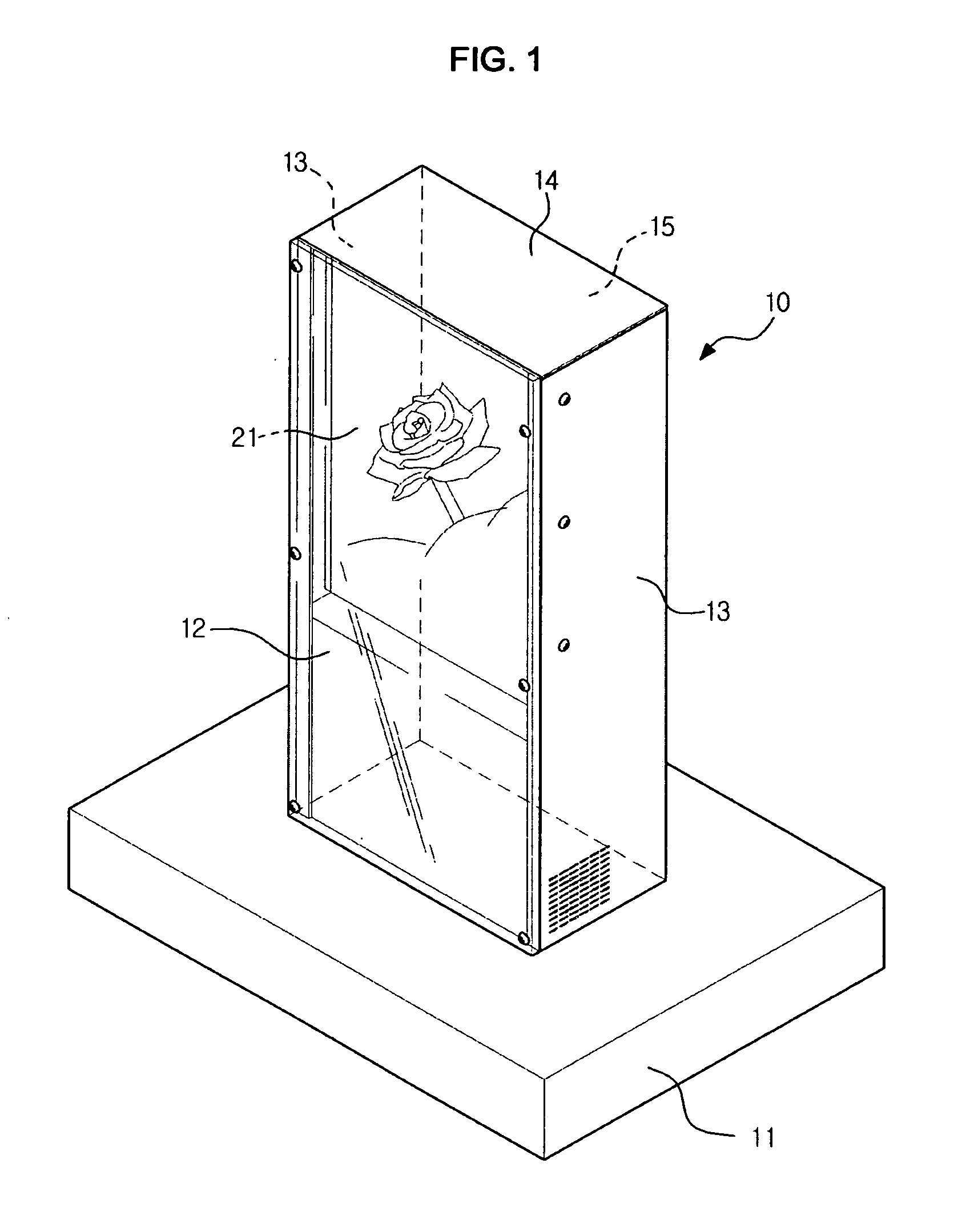
[0052]FIG. 1 is a perspective view illustrating a liquid crystal display device according to the exemplary embodiment of the present general inventive concept. A display device, such as a flat display panel or a PDP apparatus, can be used as the liquid crystal display device.

[0053]As illustrated in FIG. 1, the liquid crystal display device includes a housing 10 and a bottom plate 11 arranged beneath the housing 10 to support the same. The housing 10 includes two opposite side panels 13, a top panel 14 to join t...


PUM


Abstract

A liquid crystal display device includes a liquid crystal panel, a protection panel arranged a predetermined distant from the liquid crystal panel, and a flow control device to impart turbulence to an air flow in a channel, which is defined between the liquid crystal panel and the protection panel.

Description

CROSS-REFERENCE TO RELATED APPLICATIONS[0001]This application claims priority under 35 U.S.C. §119(a) from Korean Patent Application No. 2008-0055687, filed on Jun. 13, 2008 in the Korean Intellectual Property Office, the disclosure of which is incorporated herein in its entirety by reference.BACKGROUND OF THE INVENTION[0002]1. Field of the Invention[0003]The present general inventive concept relates to a liquid crystal display device, and, more particularly, to a liquid crystal display device with a heat dissipation structure to cool a liquid panel of the device.[0004]2. Description of the Related Art[0005]Liquid crystal display (LCD) devices are widely used in display applications such as displays of meters for automobiles and / or construction equipment, laptop computers, mobile phones, TVs, etc.[0006]An LCD device generally includes a liquid crystal panel and a backlight unit (BLU) to apply light to a rear side of the liquid crystal panel. The liquid crystal panel consists of a pa...

Claims


Application Information

Patent Timeline
IPC IPC(8): G02F1/133G02F1/1333
CPCG02F1/133385H05K7/20972G02F2201/36
Inventor KIM, JIN SUBCHO, JIN HYUNKIM, SUNG KIKANG, JOON
Owner SAMSUNG ELECTRONICS CO LTD
Why Eureka
Try Eureka