
Transmitting optical element and optical system using the same

a technology applied in the field of transmission of optical elements and optical systems, can solve the problems of unable to achieve the same way of using a transparent cover for a wide angle of view arrangement, unclear principles, and difficulty in applying them to small-format optical instruments in general and endoscopes. , to achieve the effect of high resolving power, simplified construction, and well corrected for aberrations

Inactive Publication Date: 2009-12-17
OLYMPUS CORP
View PDF7 Cites 4 Cited by
  • Summary
  • Abstract
  • Description
  • Claims
  • Application Information

AI Technical Summary

Benefits of technology

[0021]According to the invention as described above, it is possible to obtain a transmitting optical element that is of small-format size and well corrected for aberrations, has high resolving power, and is capable of taking or project a wide angle-of-view image in simplified construction.

Problems solved by technology

However, it has still been difficult to apply them to small-format optical instruments in general and endoscopes or capsule endoscopes in particular, because a lot more optical parts are required for taking images having a wide angle of view.
However, what principles underlie remains unclear.
However, nothing is still achieved about how this transparent cover is used for a wide angle-of-view arrangement.

Method used


Image

  • Transmitting optical element and optical system using the same
  • Transmitting optical element and optical system using the same
  • Transmitting optical element and optical system using the same

Examples


example 1

[0181]

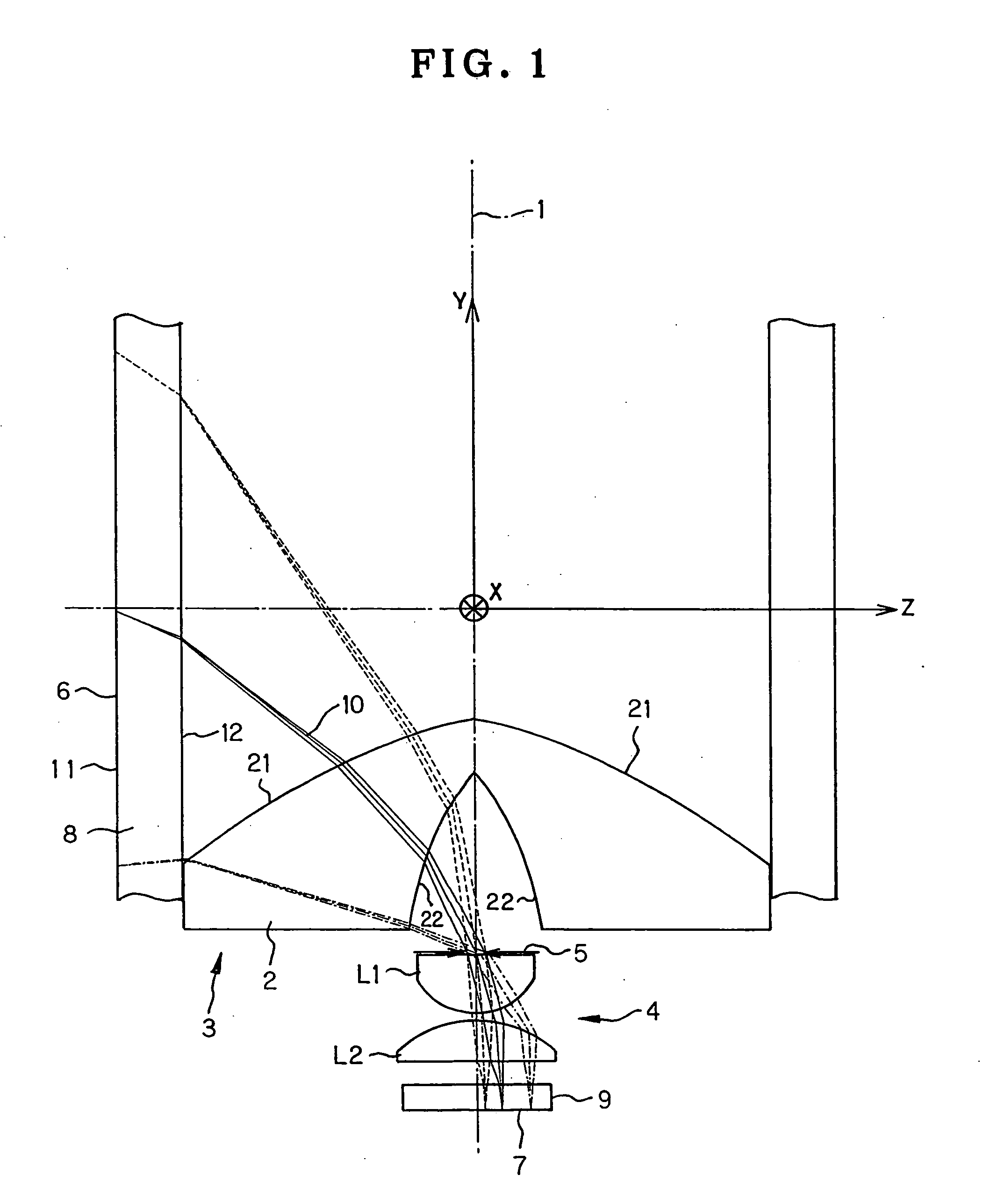
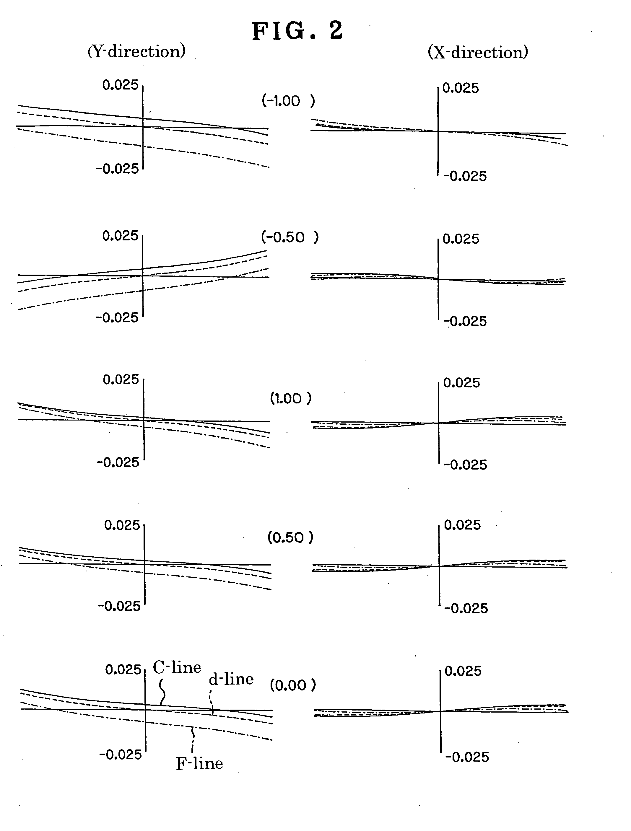
SurfaceRadius ofSurfaceDisplacementRefractiveAbbe's No.curvatureseparationand tiltindexNo.ObjectERFS[1](1)plane1ERFS[1](1)1.516364.12ERFS[2](2)3ERFS[3](3)1.516364.14ERFS[4](4)5∞ (Stop)0.03(5)5∞0.901.788047.36−1.000.1071.700.621.788047.38∞0.359∞0.401.516364.19∞0.00Image∞planeERFS[1]RY∞θ0.00R−5.50ERFS[2]RY∞θ0.00R−4.50ERFS[3]RY12.22θ−64.66R−2.01ERFS[4]RY5.23θ−20.06R−0.70Displacement and tilt (1)X0.00Y0.00Z0.00α0.00β0.00γ0.00Displacement and tilt (2)X0.00Y0.00Z0.00α0.00β0.00γ0.00Displacement and tilt (3)X0.00Y−2.41Z0.00α0.00β0.00γ0.00Displacement and tilt (4)X0.00Y−3.85Z0.00α0.00β0.00γ0.00Displacement and tilt (5)X0.00Y−5.34Z0.00α−90.00β0.00γ0.00

example 2

[0182]

SurfaceRadius ofSurfaceDisplacementRefractiveAbbe'sNo.curvatureseparationand tiltindexNo.ObjectERFS[1]plane1ERFS[1](1)1.516364.12ERFS[2](2)3ERFS[3](3)1.516364.14ERFS[4](4)5∞ (Stop)0.03(5)6∞0.901.788047.37−1.000.1081.700.621.788047.39∞0.2910 ∞0.401.516364.1Image∞planeERFS[1]RY∞θ0.00R−5.50ERFS[2]RY∞θ0.00R−4.50ERFS[3]RY5.41θ−45.79R−3.17ERFS[2]RY19.38θ0.00R−1.29Displacement and tilt (1)X0.00Y0.00Z0.00α0.00β0.00γ0.00Displacement and tilt (2)X0.00Y0.00Z0.00α0.00β0.00γ0.00Displacement and tilt (3)X0.00Y−1.13Z0.00α0.00β0.00γ0.00Displacement and tilt (4)X0.00Y−2.48Z0.00α0.00β0.00γ0.00Displacement and tilt (5)X0.00Y−4.95Z0.00α−90.00β0.00γ0.00

example 3

[0183]

SurfaceRadius ofSurfaceDisplacementRefractiveAbbe'sNo.curvatureseparationand tiltindexNo.Object∞(1)plane17.91(2)1.516364.12ERFS[1](3)3∞ (Stop)0.03(4)4∞0.301.805225.450.990.601.487570.46−0.690.1071.040.801.744044.98−0.840.301.805225.49∞0.1610 ∞0.401.516364.111 ∞0.00Image∞planeERFS[1]RY1.40θ−20.82R−0.73C49.5407 × 10−2C5−1.6486 × 10⁻²  Displacement and tilt (1)X0.00Y0.00Z−∞α0.00β0.00γ0.00Displacement and tilt (2)X0.00Y0.16Z0.00α−90.00β0.00γ0.00Displacement and tilt (3)X0.00Y−1.06Z0.00α0.00β0.00γ0.00Displacement and tilt (4)X0.00Y−3.05Z0.00α−90.00β0.00γ0.00


PUM


Abstract

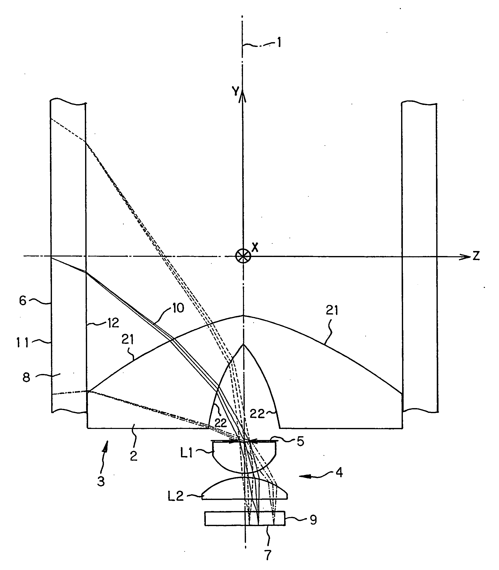
The invention relates to a transmitting optical element that is capable of taking images having a wide angle-of-view in general, and an image coming primarily from a vertical direction to a center axis in particular in simplified construction, is of small-format size and well corrected for aberrations, and an optical system using the same. The optical system is an imaging system that is adapted to form an object (6) around the center axis (1) on an image plane (7) orthogonal to the center axis (1). That imaging system comprises a front unit (3) rotationally symmetric about the center axis (1) and a rear unit (4) that is rotationally symmetric about the center axis (1) and has positive power. The front unit (3) comprises at least one transmitting optical element (2) formed of a transparent medium comprising two transmitting surfaces (21, 22) rotationally symmetric about the center axis (1) and having a refractive index of greater than 1. At least one transmitting surface (21, 22) of the transmitting optical element (2) is configured such that a normal thereto makes an angle with the center axis (1) near where the center axis (1) intersects the transmitting surface (21, 22).

Description

ART FIELD[0001]The present invention relates generally to a transmitting optical element and an optical system using the same, and more specifically to an objective or taking optical system adapted to form an image of a portion of an object having a large angle of view on a planar form of zonal image plane.BACKGROUND OF THE INVENTION[0002]Wide-angle optical systems such as fisheye lenses have so far been used as means for taking images of peripheries having a wide angle of view. However, it has still been difficult to apply them to small-format optical instruments in general and endoscopes or capsule endoscopes in particular, because a lot more optical parts are required for taking images having a wide angle of view.[0003]So far, the inner surface of a hemispherical transparent cover at the distal end of a capsule endoscope has been configured into a conical shape to achieve a wide-angle range of observation, as proposed in Patent Publication 1. However, what principles underlie rem...

Claims


Application Information

Patent Timeline
Patent Type & Authority Applications(United States)
IPC IPC(8): G02B13/06G02B3/00G02B23/24
CPCA61B1/00096A61B1/041G02B23/243G02B13/06G02B13/18A61B1/05
Inventor TOGINO, TAKAYOSHI
Owner OLYMPUS CORP
Learn More