Suspension board with circuit

Inactive Publication Date: 2009-12-17
NITTO DENKO CORP
View PDF10 Cites 18 Cited by
  • Summary
  • Abstract
  • Description
  • Claims
  • Application Information

AI Technical Summary

Benefits of technology

[0016]In the suspension board with circuit, the optical waveguide can be easily positioned through the positioning by the p

Problems solved by technology

However, when the optical waveguide 60 is routed as described above, the pro

Method used


Image

  • Suspension board with circuit
  • Suspension board with circuit
  • Suspension board with circuit

Examples


Example

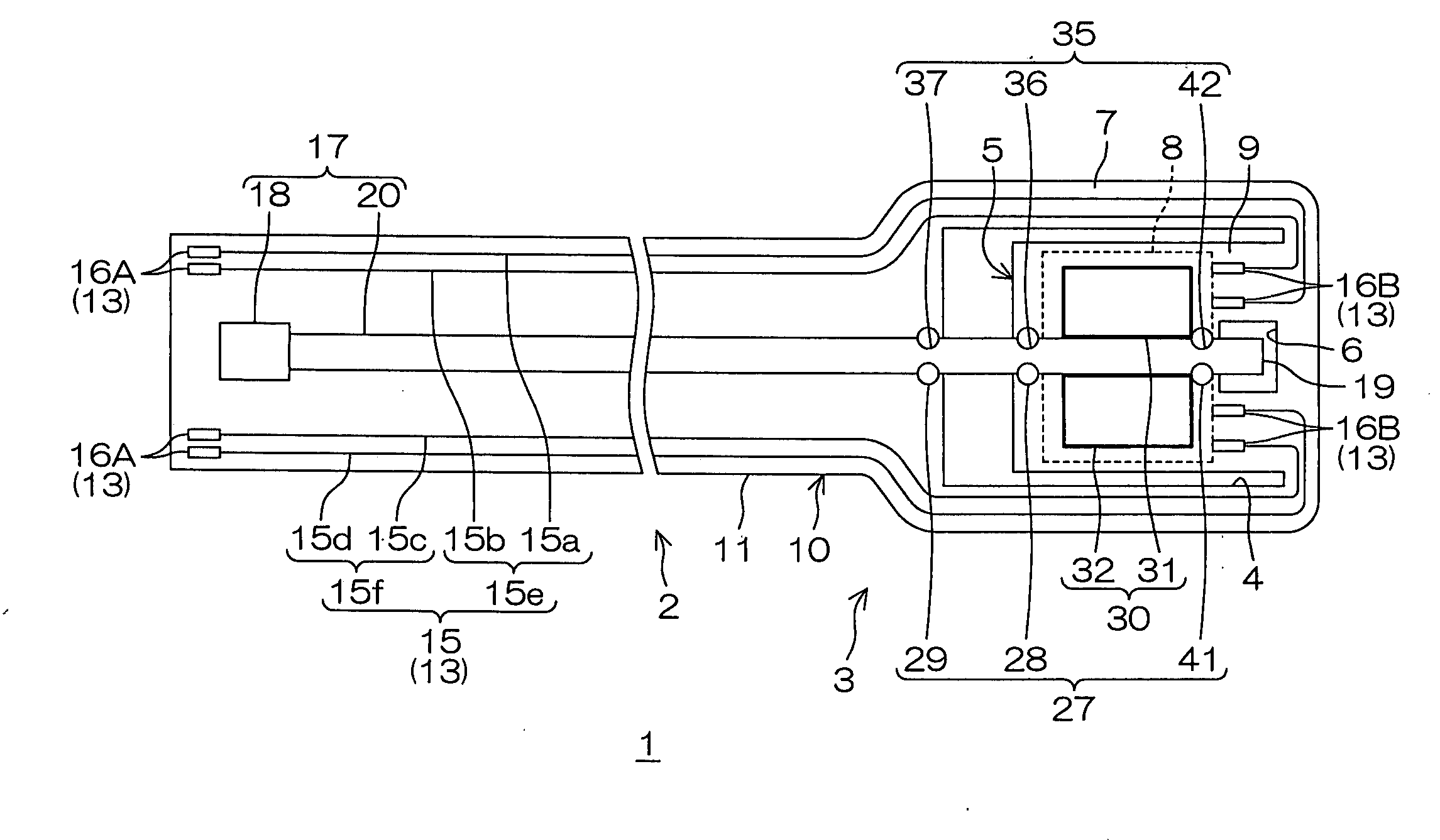
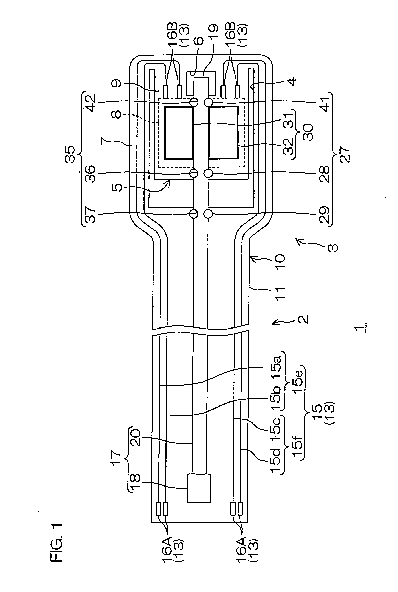
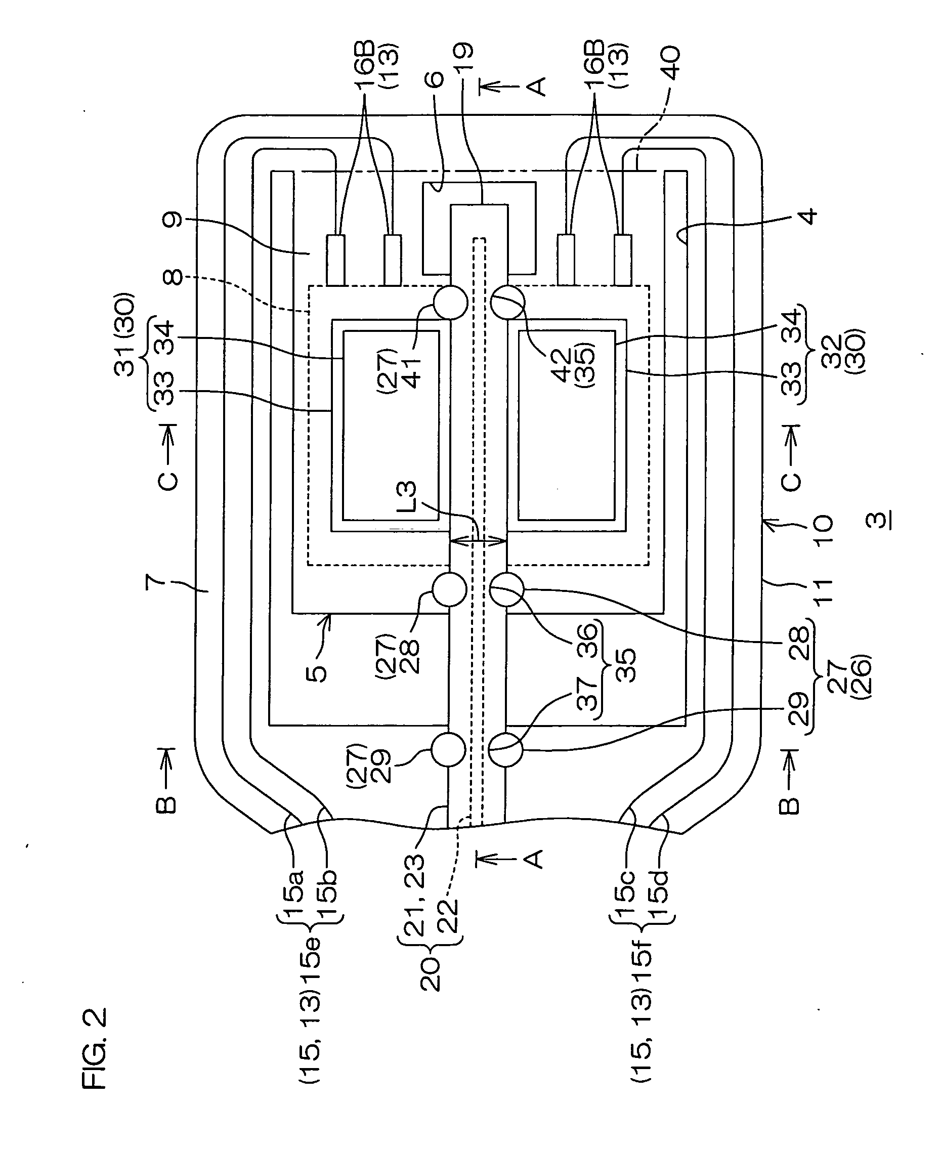
[0050]FIG. 1 is a plan view of a suspension board with circuit according to an embodiment of the present invention. FIG. 2 is an enlarged plan view of a gimbal (described later) of the suspension board with circuit shown in FIG. 1. FIG. 3 is a cross-sectional view taken along the line A-A of FIG. 2. FIG. 4 is a cross-sectional view taken along the line B-B of FIG. 2. FIG. 5 is a cross-sectional view taken along the line C-C of FIG. 2. FIGS. 6 and 7 are process views for illustrating a producing method of the suspension board with circuit, of which FIG. 6 is a cross-sectional view corresponding to FIG. 4, and FIG. 7 is a cross-sectional view corresponding to FIG. 5. FIGS. 8 and 9 are views illustrating a method of disposing the optical waveguide, of which FIG. 8 is a plan view corresponding to FIG. 2, and FIG. 9 is a cross-sectional view corresponding to FIG. 3. FIG. 10 is a view illustrating a state in which the gimbal of the suspension board with circuit shown in FIG. 1 is bent, wh...


PUM


Abstract

A suspension board with circuit includes a circuit board, and an optical waveguide formed on the circuit board. The circuit board is provided with a pedestal for supporting a slider. The pedestal allows the optical waveguide to be disposed so as to overlap the slider in a thickness direction of the circuit board.

Description

CROSS-REFERENCE TO RELATED APPLICATIONS[0001]This patent application claims the benefit of U.S. Provisional Application No. 61 / 129,387, filed on Jun. 23, 2008, and claims priority from Japanese Patent Application No. 2008-152658, filed on Jun. 11, 2008, the contents of which are herein incorporated by reference in their entirety.BACKGROUND OF THE INVENTION[0002]1. Field of the Invention[0003]The present invention relates to a suspension board with circuit and, more particularly, to a suspension board with circuit in which an optically assisted method is used.[0004]2. Description of the Related Art[0005]As a method of magnetic recording to a hard disk or the like, an optically assisted method (optically assisted magnetic recording method) has been known in recent years.[0006]For example, a thermally assisted magnetic recording head has been proposed which includes a suspension, and an optical waveguide (second optical waveguide) provided thereon, and connected to a laser diode (see, ...

Claims


Application Information

Patent Timeline
IPC IPC(8): G02B6/12
CPCG02B6/43G11B5/4833H05K1/056G11B2005/0021H05K1/0274G11B5/4866
Inventor KANAGAWA, HITOKIISHII, JUNNAITO, TOSHIKI
Owner NITTO DENKO CORP
Why Eureka
Try Eureka