Fixing device and image forming apparatus including same

a technology of fixing device and fixing belt, which is applied in the direction of electrographic process apparatus, instruments, optics, etc., can solve the problems of fixed belt and belt member wear, fixed belt and fixing belt wear, and relatively short operating life of fixing devi

Active Publication Date: 2009-12-17
RICOH KK
View PDF13 Cites 74 Cited by
  • Summary
  • Abstract
  • Description
  • Claims
  • Application Information

AI Technical Summary

Problems solved by technology

In such fixing devices, because the fixed member slidingly contacts the inner circumferential surface of the belt member for a relatively long time period, both the fixed member and the belt member experience wear.
For example, in the above-described known fixing device, the fixed member and the fixing belt can wear out over time because sliding resistance between the fixing belt and the fixed member is relatively large, and accordingly the operational life of the fixing device can be relatively short.
Additionally, driving torque of the fixing device is relatively high due to the high sliding resistance between the belt member and the fixed member, which might cause the belt member to slip, disturbing a fixed image, which is a phenomenon so-called “image slip”.
Relatively high driving torque of the fixing device can also damage a teeth of a driving...

Method used


Image

  • Fixing device and image forming apparatus including same
  • Fixing device and image forming apparatus including same
  • Fixing device and image forming apparatus including same

Examples


Embodiment Construction

[0032]In describing preferred embodiments illustrated in the drawings, specific terminology is employed for the sake of clarity. However, the disclosure of this patent specification is not intended to be limited to the specific terminology so selected and it is to be understood that each specific element includes all technical equivalents that operate in a similar manner and achieve a similar result.

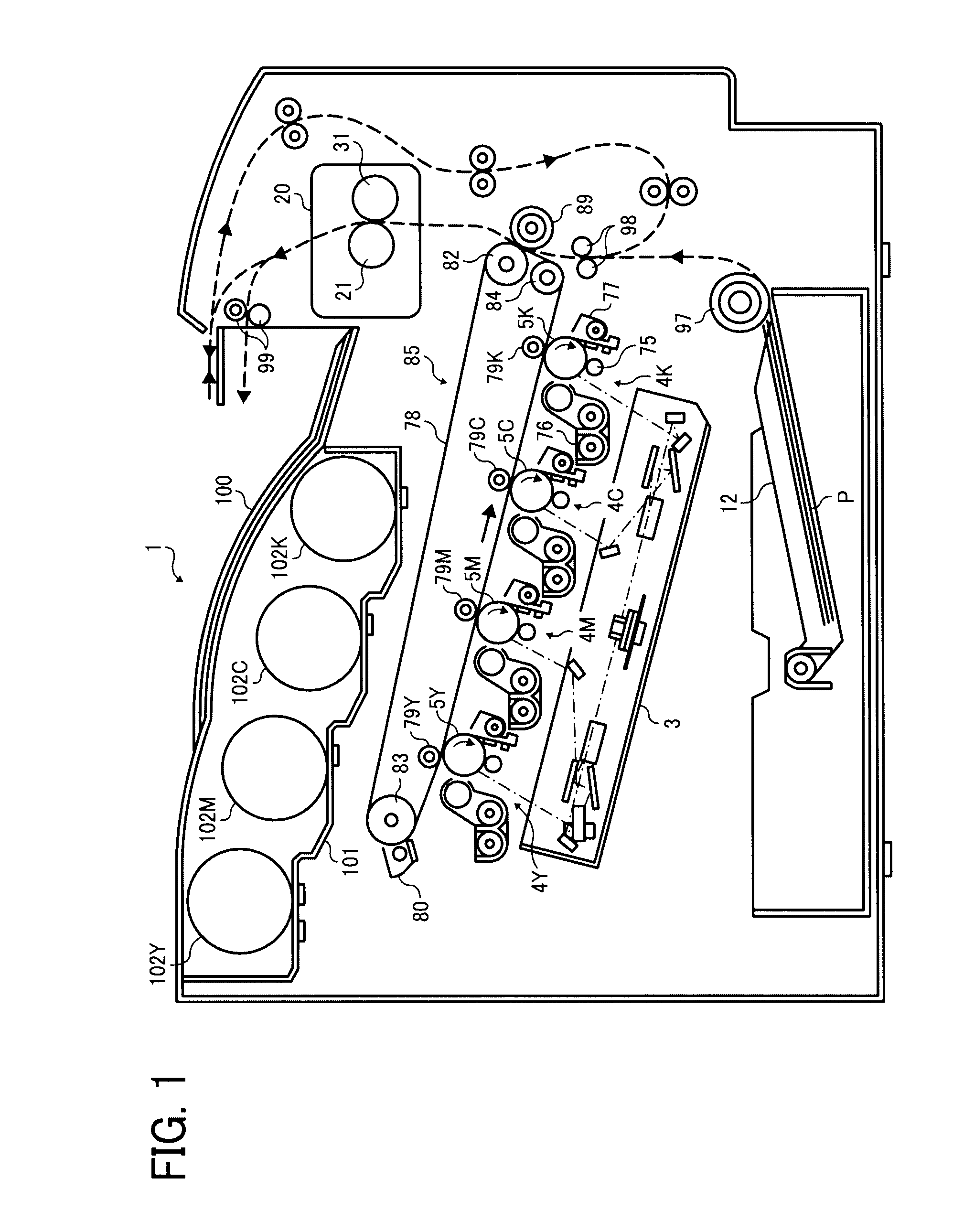
[0033]Referring now to the drawings, wherein like reference numerals designate identical or corresponding parts throughout the several views thereof, and particularly to FIG. 1, an image forming apparatus according to an illustrative embodiment of the present invention is described. It is to be noted that, in the description below, reference characters Y, M, C, and K represent yellow, magenta, cyan, and black, respectively, and may be omitted when color discrimination is not required.

[0034]FIG. 1 illustrates an image forming apparatus 1 that in the present embodiment is a tandem multicol...


PUM


Abstract

A fixing device to fix a toner image on a sheet includes a flexible endless belt that rotates in a predetermined direction, an inner circumferential surface of which includes a fluorine-containing surface layer, a rotary member that contacts an outer circumferential surface of the belt, a fixed member fixed inside the belt to press against the rotary member via the belt, forming a nip portion therebetween, a lubricant applied between the belt and the fixed member, and a heat source to heat at least one of the belt and the rotary member. A surface of the fixed member that slidingly contacts the inner circumferential surface of the belt includes a fluorine-containing surface layer. One of the fluorine-containing surface layers is porous, and at least one of the fluorine-containing surface layers has a surface energy greater than a surface tension of the lubricant.

Description

CROSS-REFERENCE TO RELATED APPLICATIONS[0001]This patent specification claims priority from Japanese Patent Application Nos. 2008-157105, filed on Jun. 16, 2008 and 2009-002307, filed on Jan. 8, 2009 in the Japan Patent Office, the entire contents of each of which are hereby incorporated by reference herein.BACKGROUND OF THE INVENTION[0002]1. Field of the Invention[0003]The present invention generally relates to a fixing device used in an image forming apparatus such as a copier, a printer, a facsimile machine, or a multifunction machine including at least two of these functions, and an image forming apparatus including the fixing device.[0004]2. Discussion of the Background[0005]In general, electrophotographic image forming apparatuses, such as copiers, printers, facsimile machines, and multifunction machines including at least two of these functions, include an image carrier on which an electrostatic latent image is formed, a developing unit to develop the latent image with toner,...

Claims


Application Information

Patent Timeline
IPC IPC(8): G03G15/20
CPCG03G15/2025G03G2215/2035
Inventor SHINSHI, AKIRA
Owner RICOH KK
Why Eureka
Try Eureka